Electrical circuits of the car that consume high current are protected by fuses

The inserts are installed in a common block (VPR-4.10), fixed in the engine compartment on the right side and closed with a plastic cover.
The starter circuit is designed for high short-term current, so there is no fuse.
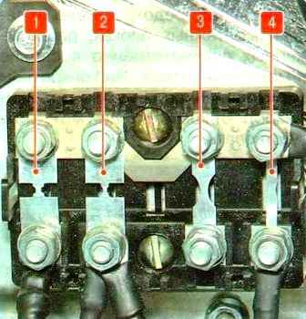
To replace a burned-out insert bar, squeeze the two latches on the unit cover and remove the cover.

Spare inserts of different denominations are fixed under the block cover plate.

Remove the two nuts of the burnt insert and replace the insert.
Low-voltage electrical circuits are also protected by fusible links, which are located in the mounting blocks in the passenger compartment and in the engine compartment.

To access the mounting block in the cabin, pull the edges of the two recesses in the lower decorative shield and remove the shield.

On the inside of the shield there is a diagram of the location of relays and fuses
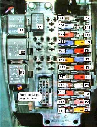
Assignment of fuses and relays in the mounting block located in the passenger compartment
No. - A - Protected circuit
- F1 - 20 - Wiper, washer
- F2 - 10 - Lighting control module, instrument lighting
- F3 - 5 - Power mirrors
- F4 - 25 - Power windows
- F5 - 10 - Heated exterior mirrors
- F6 - 10 - Heated driver's seat
- F7 - 15 - Additional heater
- F8, F11, F12 - Reserve
- F9 - 10 - Locking Differential
- F10 - 15 - Second row power outlet
- F13 - 7.5 - Daytime running lamps
- F14 - 5 - Rear fog lamps
- F15 - 10 - Direction indicators
- F16 - 7.5 - Instrument cluster, speed sensor, heater control
- F17 - 5 - Engine Management
- F18 - 5 - Anti-lock braking system
- F19 - 20 - Cigarette lighter socket
- F20 - 15 - Hazard lights
- F21 - 15 - Light control module, backlight
- F22 - 10 - Interior lighting
- F23 -15 - Central locking, audio system
- F24 - 5 - Instrument cluster, diagnostic connector, preheater control panel
Relay
- K1 - Wiper
- K2 - Heater
- K3 - Instrument switch and starter power circuit
- K4 - Coolant heater
Part of the fuses and relays is located in the mounting block in the engine compartment
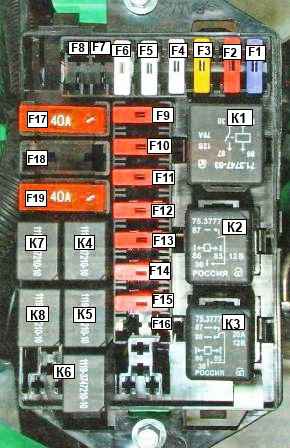
Assignment of relays and fuses in the mounting block located in the engine compartment
No. - A - Protecting my chain
- F1 - 15 - Fog lamp relay coil
- F2 - 10 - Stop lights
- F3 - 20 - Horn relay coil
- F4 - 25 - Fuel heater relay coil
- F5 - 25 - Coolant heater
- F6 - 25 - Instrument and starter switch
- F7 - 25 - Anti-Lock Braking System (ABS)
- F8 - Reserve
- F9 - 10 Low beam (left headlight)
- F10 - 10 Low beam (right headlight)
- F11 - 10 - High beam (left headlight)
- F12 - 10 - High beam (right headlight)
- F13 - 10 - Dimension lamps (left side)
- F14 - 10 - Dimension lamps (right side)
- F15 - 10 - Reversing lamps
- F16 - Reserve
- F17 - 15 - Heater
- F18 - 25 - Anti-lock braking system (ABS)
- F19 - reserve
Relay
- K1 - Starter relay
- K2 - Fuel heater relay
- K3 - Brush reset relay
- K4 - Low beam relay
- K5 - High beam relay
- K6 - Fog lamp relay
- K7 - Horn relay
- K8 - Starter Interlock Relay
To access the mounting block in the engine compartment:

Press the lid lock in the direction of the arrow

Remove the cover
Before replacing a blown fuse, you need to find out the cause of the blown fuse or relay.
Replacing the relay-interrupter of the direction indicator
Tools required: 19 socket, slotted and Phillips screwdrivers.

Remove the steering wheel

Removing the left steering column switch (article - Replacing Gazelle Next steering column switches)

Remove the relay from the base of the switch by gently rocking the relay body from side to side
Install the relay and all parts in reverse order.

")
")
")
")