


Figure 1 shows the wiring diagram of the electronic engine management system for the Foton Aumark ISF3.8 CM2220 without SCR from 2010 onwards.
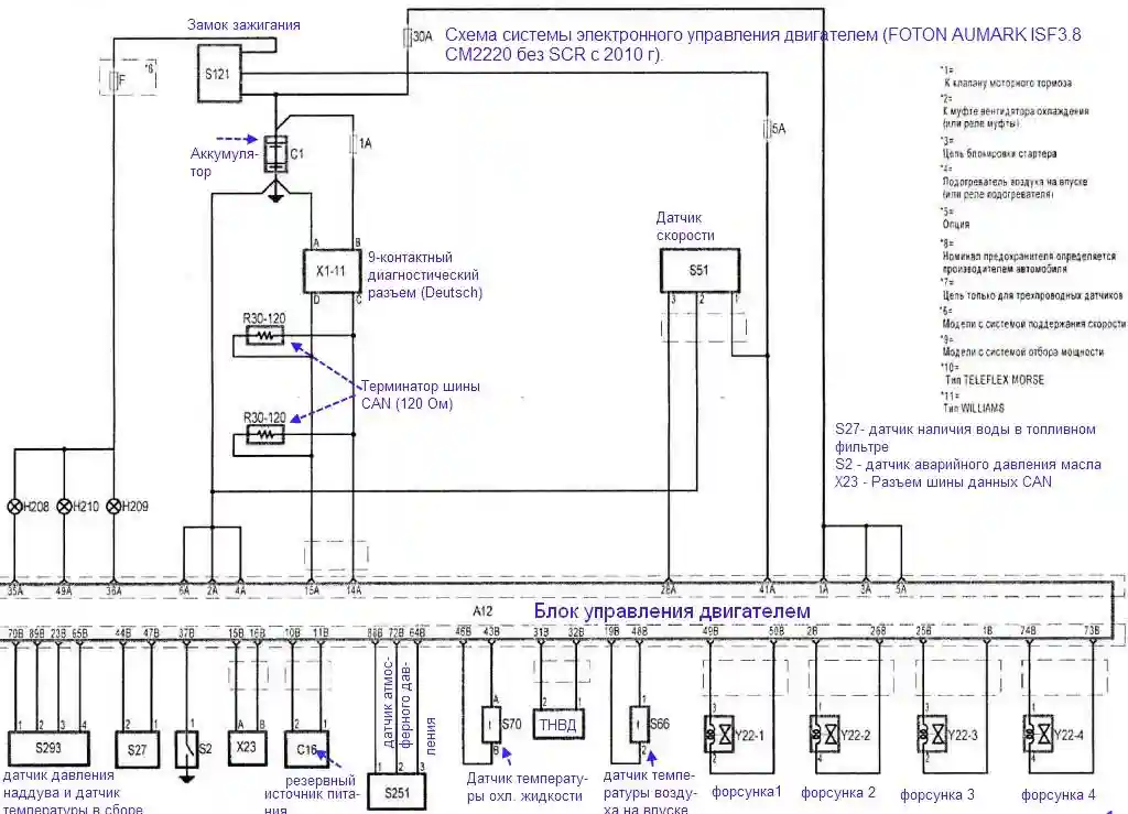
Figure 2 shows the continuation of the wiring diagram for the electronic engine management system of the Foton Aumark ISF3.8 CM2220 without SCR from 2010 onwards.
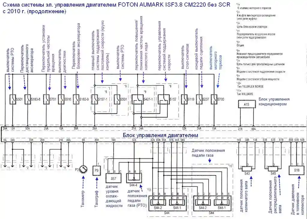
Figure 3 shows the wiring diagram of the electronic engine management system for the Foton Aumark ISF3.8 CM2220 with SCR from 2010 onwards.
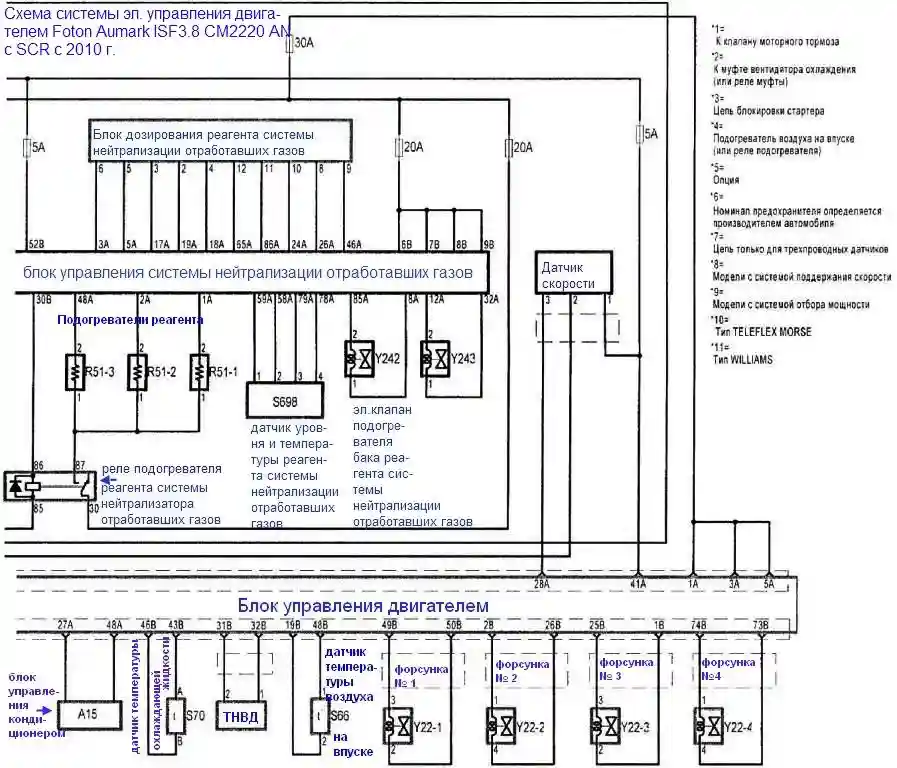
Figure 4 shows continuation 1 of the wiring diagram for the electronic engine management system of the Foton Aumark ISF3.8 CM2220 with SCR from 2010 onwards.
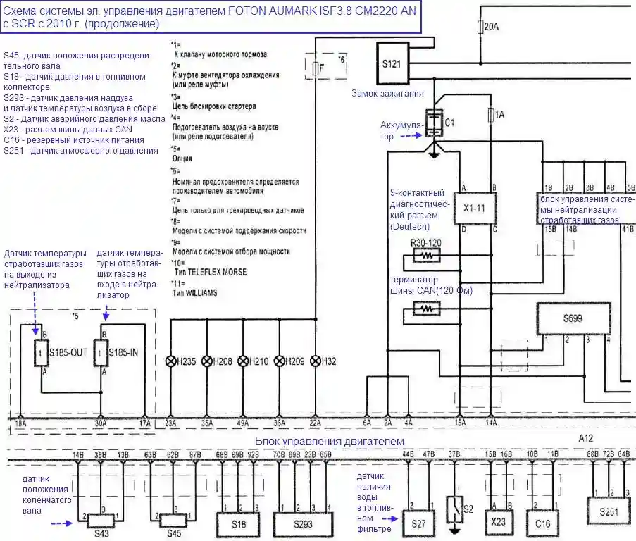
Figure 5 shows continuation 2 of the wiring diagram for the electronic engine management system of the Foton Aumark ISF3.8 CM2220 with SCR from 2010 onwards.
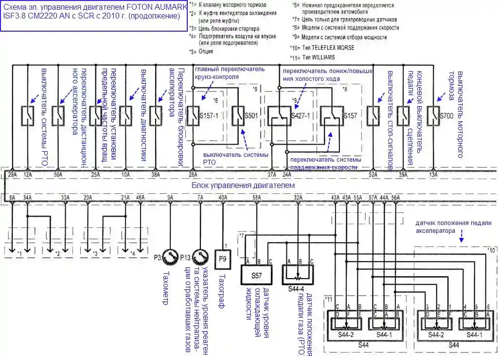
The diagrams above cover the electrical circuits of the sensors, actuators and the engine control module (ECM) of the Cummins ISF3.8 engine in CM2220 configuration: both the variant without selective catalytic reduction (SCR) and the variant with SCR. These diagrams are intended for diagnostics, fault-finding and repair of the electrical system on Foton Aumark vehicles built from 2010 onwards.


