
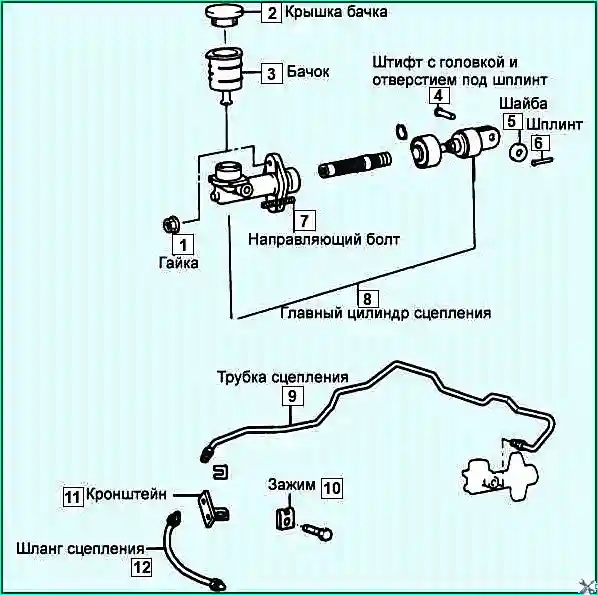
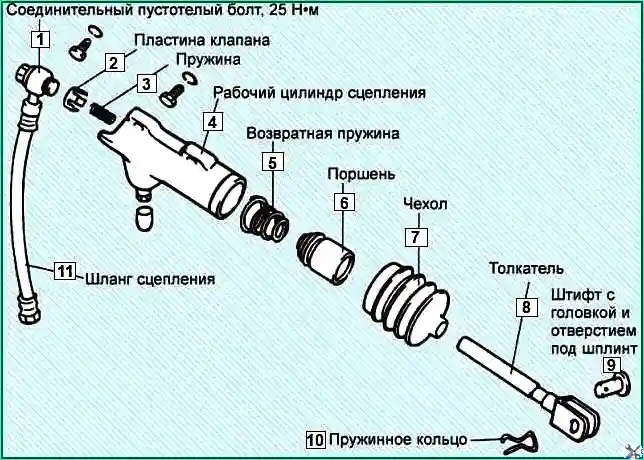
Removing the clutch components for replacement or repair
Preparing the vehicle for the task. Placing the vehicle on a lift or inspection pit
Unscrew the drain plug on the slave cylinder and drain the clutch fluid
Remove the cotter pin, washer and pin
Disconnect the tube from the clutch master cylinder side

Unscrew the clutch master cylinder mounting bolt

Remove the clutch tube clamps
Unscrew the nut on the clutch tube, having first fixed the nut on the clutch hose
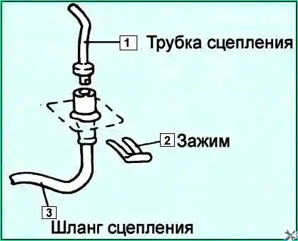
Remove the clamp and disconnect from the bracket

Remove the clutch hose
Disconnect the clutch hose from the clutch slave cylinder
Check the hose and clutch tube for cracks and clogging
Disassembling the clutch master cylinder
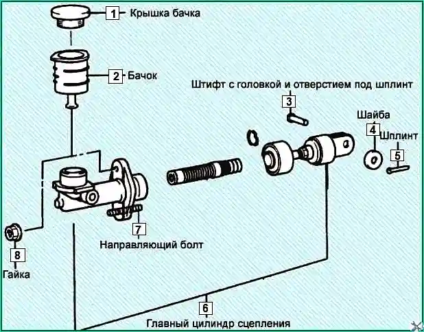
Clamp the master cylinder in a vice

Remove the piston axe ring
Take out the pusher and piston
Remove the reservoir mounting tape, reservoir and cover
Do not damage the pusher and the surface of the clutch master cylinder
Do not disassemble the piston assembly
Check
Check the inside of the housing cylinder for rust, pitting or wear.
Clean dismantled parts in solvent and blow out all parts and passages with compressed air.
Check piston seal for wear.
Check piston for rust, pitting or wear.
Check clutch hydraulic tube for damage.
Measure the inside diameter of the clutch master cylinder and the outside diameter of the piston.
Make measurements of the inside diameter of the clutch master cylinder in three sections (base, center and top) in two perpendicular directions.
If the clearance between the piston and cylinder exceeds the permissible value, replace the master cylinder and / or piston assembly.
Gap: 0.15 mm
Assembly
Before assembly, lubricate the piston and the inner cavity of the cylinder with clutch fluid
Install the piston assembly

Connect the clutch hose to the clutch slave cylinder

Manually tighten the nut securing the hose to the tube, then tighten to the recommended torque

Installing the clamps for fastening the hose to the bracket

Installing the clutch master cylinder
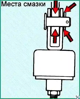
Before installation, lubricate the bushing and pin with SAE J 310, NGLI No. 2 grease
Install the pusher on the clutch pedal
Fill the fluid into the clutch master cylinder
Bleed the clutch hydraulic drive
Removing and repairing the clutch slave cylinder

Unscrew the drain plug (A) and drain the clutch fluid
Fix the clutch hose between the clutch slave cylinder and the tube
Unscrew the slave cylinder mounting bolt and remove the slave cylinder
Install the slave cylinder in the reverse order
Disassembling the slave cylinder
Remove the clutch hose, valve plate, spring, pusher and boot
Remove dirt from the piston hole in the clutch cylinder

Removing piston and cuff, supplying compressed air through the hole for connecting the hydraulic tube while:
- close the hole of the working cylinder with a rag in order to catch the piston pushed out by the compressed air.
Check the working cylinder for damage

Measuring the inner diameter of the clutch working cylinder
Measuring the inner diameter of the clutch master cylinder is carried out in three sections (at the base, center and top) in two perpendicular directions.
If the clearance between the piston and the cylinder exceeds the permissible value, replace the master cylinder and/or the piston assembly.
Gap: 0.15 mm
Removing and installing clutch discs
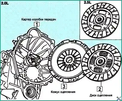
Removing the manual gearbox
To remove the gearbox, you need to remove the air filter connections, bracket, disconnect the wires and etc.

Remove the release lever, for this:
- - unscrew the release lever mounting nuts
- - remove the pin and spring ring from the clutch cylinder
- - remove the release lever
Unscrew the bolts and remove the clutch release cylinder
Unscrew the bolts securing the gearbox to the engine and remove the gearbox

Using pliers, remove the clutch release bearing from the diaphragm spring of the clutch housing

Rotate the clutch bearing in any direction to determine the position of the snap ring.

Insert the pliers under the wave washer, as shown in the figure and place it in the center snap ring.
Increase the space around the snap ring by pressing on the bearing as shown in the figure
Expand the snap ring as shown in the figure

Keeping the snap ring in an expanded state, remove the clutch release bearing
Install a mandrel for centering the clutch disc
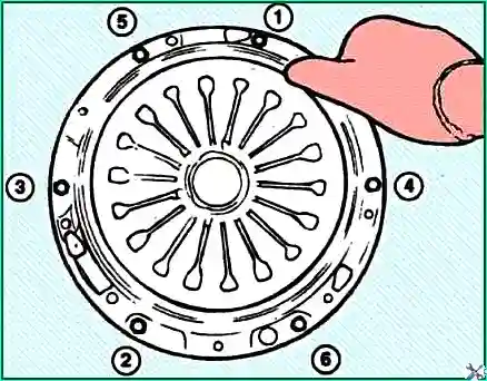
Gradually loosen the clutch basket mounting bolts diagonally, turning each bolt half a turn until the action stops diaphragm spring, and then unscrew all the bolts manually
Remove the clutch housing with the pressure plate and clutch disc
Remove the fork shaft and bushing
Checking the clutch discs
Clean the dust from the clutch housing using a vacuum brush or vacuum cleaner. Do not use compressed air.
Remove the flywheel and check the rear crankshaft seal ring for leaks. Replace the seal ring if necessary.
Check the pressure plate for cracks, burns, and surface wear.
Check the flywheel friction surface for partial damage, cracks, and wear.

Check the condition of the clutch disc friction linings and replace the clutch disc if there are traces of oil or mechanical damage.
Check the protrusion of the friction linings above the rivet heads. If the protrusion is less than the permissible value, replace the clutch disc.
Protrusion: 0.3 mm
Check the hub splines and clutch disc damper springs for excessive wear.
Clean the friction surface of the pressure plate with a cleaning solvent.
Check the diaphragm spring at the points of contact with the clutch release bearing for wear, cracks and determine the difference in the height of the diaphragm spring ends.
If present, defects, replace the clutch housing with the pressure plate.
Difference in height of the diaphragm spring ends: 0.5 mm
Make sure that the flywheel has three guide pins for centering the clutch housing.
The clutch release bearing is sealed and cannot be washed.
Check the condition of the clutch release bearing, which should rotate easily, evenly and quietly and should be free of play.
The working surface of the bearing acting on the pressure spring should be smooth, without cracks, local corrosion or wear.
If there is uneven wear at the points of contact between the bearing and the clutch release fork, replace the clutch release bearing.
If there is uneven wear at the points of contact between the clutch release fork and the bearing, replace the release fork clutch.
Installation
Apply grease to the splines of the clutch disc.

Lubricant: CASMOLY L 9508
When installing the clutch, apply grease to all moving parts, but do not use an excessive amount of grease, as this may cause the clutch to slip.
Install the clutch disc and center it with a special mandrel 09411–11000.
Install the clutch housing with the pressure plate on the flywheel guide pins.
Gradually, in a diagonal sequence and in a specific order, tighten the clutch housing bolts.
Tightening torque:
- Engine 2.0L: 15–22 Nm
- 2.5L Engine: 20–27 Nm

Align the clutch release bearing, release the snap ring and install the bearing on the clutch housing sleeve.
Apply CASMOLY L9508 universal grease to the support sleeve and contact points of the clutch release fork.

Install the release lever to the release fork.
If the transmission is installed to the engine without performing this step, the clutch release bearing may be disconnected because the release fork rotates freely.
Install the transmission to the engine.

Then, press the release lever in the direction of the arrow to move the cam, which will ensure that the clutch release bearing and clutch housing are installed correctly.
Release lever stroke: no more than 3°
If the release lever stroke is more than 3°, the clutch release bearing and clutch housing are not installed correctly.

")
")
")
")
")
")
")
")