
To prevent damage to the paintwork of the body wings, it is necessary to use a special coating
To prevent damage to the cylinder head, wait until the engine cools down before removing it
When removing the metal cylinder head gasket, be careful not to miss it or damage the contact surface of the block with the head
When disconnecting the wiring, apply force directly to the connector, but not to the wire.
To avoid incorrect connection, it is necessary to apply marks to all wires.
Turn the crankshaft pulley to set the piston of the first cylinder to the top dead center (TDC) position.

Remove the air duct (A) and the battery (B), having previously disconnected the positive and negative terminals.

Remove the engine cover (A).

Disconnect the air intake hose and air filter in assembly.
Disconnect the mass air flow sensor connector (A).
Disconnect the vent hose (B) from the air cleaner hose.
Remove the air intake hose and air cleaner assembly (C).

Disconnect the PCM connector (D).

Remove the upper and lower radiator hoses (B).

Remove the fuel inlet hose (A) from the main pipeline.
Disconnect the electrical connectors.

Disconnect connectors No. 1, No. 2 of the knock sensor (A, B), injectors (C), ignition coil wiring (D) and connector No. 1 VIS (E).

Disconnect the connectors of the oxygen sensor of the 1st row.

Disconnect the connectors of the high-pressure tube (A, B C), ground wires (D). condenser (E) and ignition coil (F).

Disconnect connectors No. 1 and No. 2 of valves (A, B) and the oil temperature sensor (C).

Disconnect the connectors of the absolute air pressure sensor (A), throttle position controller (B) and positive crankcase ventilation pipe (C).

Disconnect the connector of the generator (A) and the air conditioning compressor (B).

Disconnect the connector of the camshaft position sensor of bank No. 2 and the coolant temperature sensor (B).

Disconnect the connectors of the oxygen sensor of bank №2 (A, B) and the crankshaft position sensor (C).

Disconnect the connector of the camshaft position sensor of row №1 (A).

Disconnect the brake vacuum hose (A).
Remove the heating hoses.

Remove the drive belt (A) of the auxiliary equipment.

Remove the power steering pump.
Remove the exhaust manifold assembly.
Remove the intake manifold assembly.
Remove the timing belt.
Remove the ignition coils.
Remove the thermostat.
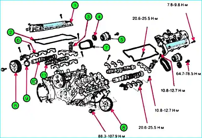
Remove the cylinder head cover (A).

Remove the camshaft bearing cap (A).

Remove the timing chain tensioner (A).

Remove the camshaft.
Remove the rear cover of the drive belt of row No. 2 (A).

Remove the rear cover of the drive belt of row №1 (A).

Remove the bracket of the position sensor connector crankshaft (A)
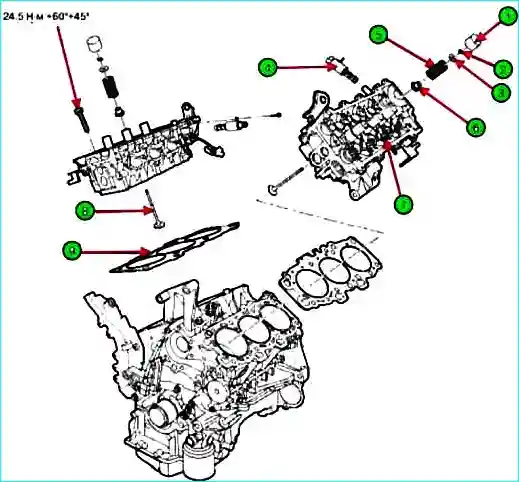
Remove the cylinder head assembly.

Remove the bolts in 2-3 steps in the order shown in the figure.
Installation inconsistency may result in damage to the cylinder head.
After removing the cylinder head, place the block on a wooden surface.
Make sure that the surface between the cylinder head and the block is not damaged.
Installation
Before installation, clean all parts,
Always use a new cylinder head gasket and exhaust manifold gasket.
Always use new cylinder head bolts.
The cylinder head gasket is metal, be careful not to damage it.
Turn the crankshaft to set the piston of the first cylinder to the TDC position.

After installing the cylinder block gasket, install the cylinder head.
When installing, specify the dimensions of the left and right cylinder head gaskets.

Tighten the cylinder head bolts with the washer in the following order:
When assembling the washer, the marked surface should be on top.
When installing the bolts, apply engine oil to the threads of the bolts and the surface of the washers. Tightening torque: 24.5 Nm.

Using a special device (09221-4A000), tighten the bolts using the angular tightening method.
Install the phase shifter assembly and the timing chain sprocket with the positioning pin in the phase shifter, installed on the intake camshaft.
Make sure that the pin is not installed in the oil feed hole. Tightening torque: 66.7 - 78.5 Nm.
After installing the phase shifter bolts, turn the phase shifter assembly counterclockwise by hand, place the pin in the appropriate position.
Fix the hexagonal area of the camshaft with a vice, then tighten the bolts. Do not lock the phase shifter or sprocket.
Install the camshaft onto the cylinder head assembly.
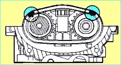
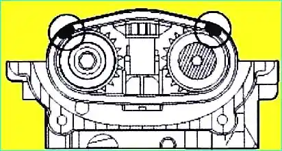
Align the marks on the intake and exhaust camshaft chain sprockets and the timing chain.
Both marks must be at the top for assembly
Install the intake and exhaust camshafts onto the cylinder head, aligning the marks.

Install the timing chain tensioner.
Install the pin by pressing on the chain tensioner.
Install the tensioner (A) on the cylinder head.
Remove the pin from the tensioner after installation.

Install the camshaft bearing caps. Tightening torque: bolt (A: 6x38): 10.8 - 12.7 Nm, bolt (6: 8x38): 20.6 - 22.5 Nm.
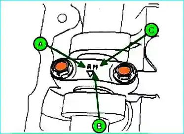
When installing the bearing caps, check for marks as shown in the figure and install them into the correct position.
When installing the bearing caps, rotate the crankshaft to position the piston in the middle of the block, because there may be a collision between the valve and the piston.

Using a special device (09214-21000), install the camshaft oil seal.
Apply engine oil before installation
The camshaft cover must be firmly attached to the cylinder head assembly.
Do not create an eccentric load.

Install the camshaft sprocket.
Hold the hexagonal area of the camshaft in a vice and screw in the bolts. Tightening torque: 88.3 - 107.9 Nm.
If the camshaft is replaced with a new one, check the valve clearance, then install the tappet.
To prevent the valve and piston from colliding, rotate the crankshaft sprocket 3 turns from the TDC of the first cylinder, then measure the valve clearance.

Install the crankshaft position sensor connector bracket.

Install the rear cover (A) of the first row timing belt.

Install rear cover (A) of the second row timing belt.
The length of bolt B is greater than the length of bolt C.
Install the cylinder head cover
Remove oil, dust and sealant from the cylinder surface before assembling the cylinder head cover.

Assemble the cylinder head cover five minutes after applying sealant to the camshaft cover.

Tighten the cylinder head bolts in the correct order (A). Tightening torque: 7.8 - 9.8 Nm.
Do not start the engine for 30 minutes after installing the cylinder head cover.
Do not install the old cylinder head gasket.
Install the timing belt.
Align the marks on the left and right camshaft sprockets.
Prevent the valve and piston from colliding, rotate the crankshaft sprocket 3 turns from TDC of the first cylinder, then align the marks on the sprockets.
After aligning the marks on the camshaft sprockets, rotate the crankshaft sprocket 3 turns clockwise and align the crankshaft sprocket mark to set the piston of the first cylinder to TDC.
Install the belt Timing belt.
Install the thermostat assembly.
Install the intake manifold assembly.
Install the exhaust manifold assembly.
Install the power steering pump.
Install the drive belt (A).

Install the heater hose.
Connect the brake vacuum hose (A).
Connect the wiring connectors engine.

Connect the connector of the first row camshaft position sensor (A).

Connect the connectors of the crankshaft position sensor (C), the front and rear oxygen sensors (A, B) of the second row.

Connect the connectors of the water temperature sensor (B) and the camshaft position sensor (A) of the second row.

Connect the connectors of the generator (A) and the air conditioning compressor (B).

Connect the connectors of the absolute oil pressure sensor (A), the throttle position sensor (B) and the positive crankcase ventilation valve (C).

Connect the connectors of valves 1 and No. 2 (A, B) and the oil temperature sensor (C).

Connect the injector connectors (A, B, C), ground wires (D), condenser (E) and ignition coils (F).

Connect connectors of the front and rear oxygen sensor (A) of the first row.

Connect the connectors of knock sensors No. 1 and No. 2 (A, B), injectors (C), ignition coil wiring (D) and VIS (E).

Install the fuel inlet hose (A) to the main pipe.

Install the upper (A) and lower (B) radiator hose.

Install the air intake hose and air filter assembly.
Connect the PCM connectors (D).
Install the air intake hose and air filter assembly (C).
Connect the ventilation hose (B) to the filter hose.
Connect the mass air connector sensor connector.

Fill in coolant.

")
")
")
")
")
")
")
")