
The drive shafts transmit torque from the engine, gearbox and differential to the front wheels
The drive shafts are splined to the differential axle gears in the gearbox housing.
The splined end of the inner joint of the drive shaft is fixed in the axle gear by a spring retaining ring.
When installed, the retaining ring is compressed, entering the groove of the shaft.
After the shaft is fully installed in the differential axle gear, the retaining ring is released and fixes the splined end from axial movement.
The outer joints of the drive shafts are attached to the hubs of the front wheels, mounted on bearings.
The shaft is fastened to the hub with a nut with flange.
To prevent the nut from loosening, the flange of the nut is bent into the recess of the drive shaft.
Constant velocity joints (CV joints) are installed on both sides of the drive shaft.
All outer CV joints are Birfield type, and the inner ones are tripod or ball type.
Tripod type CV joints are used to prevent engine vibrations from being transmitted through the drive shafts to the car body.
CV joints are necessary for transmitting torque and compensating for front suspension movement.
Also, CV joints allow you to change the length of the drive shaft and transmit torque at constantly changing angles.
Removing the drive shafts
Prepare the car and install it on a lift or inspection pit
Lift the car and secure it on supports and remove the front wheel
Drain the transmission fluid from the gearbox

Remove the cotter pin and unscrew the nut securing the drive shaft to the front wheel hub

Unscrew the two bolts and disconnect the ball joint from the hinge

Using a hammer with a plastic striker, knock the drive shaft out of the front wheel hub
If the drive shaft fits tightly in the front wheel hub, spray WD-40 on the spline area and then screw the nut back on a few turns, but do not tighten it.
Hit the nut with a hammer with a soft striker, knock the drive shaft out of the hub.
Tilt the steering knuckle outward and remove the drive shaft from the front wheel hub

Then insert a crowbar between the gearbox housing and the drive shaft and lightly tap the crowbar to remove the drive shaft from the gearbox (except for V 6)
Do not pull the drive shaft, as this will damage the constant velocity joints
Do not insert the crowbar too deeply, so as not to damage oil seal

Do not lower the car onto its wheels with the drive shafts disconnected, as this will damage the hub bearing.

If it is necessary to place the vehicle on its wheels for moving it, use a special tool to support the hub bearing.
Release the tensioner mechanism and remove the drive belt (V6 engines)

Removing the generator (V6 engines)
Unscrew the mounting bolts securing the central bearing bracket.

Insert the crowbar between the central bearing and cylinder block and disconnect the bracket from the cylinder block.
Remove the inner joint of the drive shaft from the gearbox

Using a puller, remove the ABS sensor rotor from the drive shaft
Checking the drive shaft
Check the protective covers of the CV joints of the drive shaft for defects

Check the splines on the ends of the drive shaft for wear and damage
Installing the drive shaft
Lubricate the working lip of the differential oil seal.
Install a new snap ring on the inner end of the drive shaft.
Push the drive shaft into the gearbox with the split in the snap ring facing down.
After installation, pull the drive shaft outward and make sure it is securely held in place with the round clamp.

Install the washer under the drive shaft to hub mounting nut with the convex side facing outward, as shown in the figure.
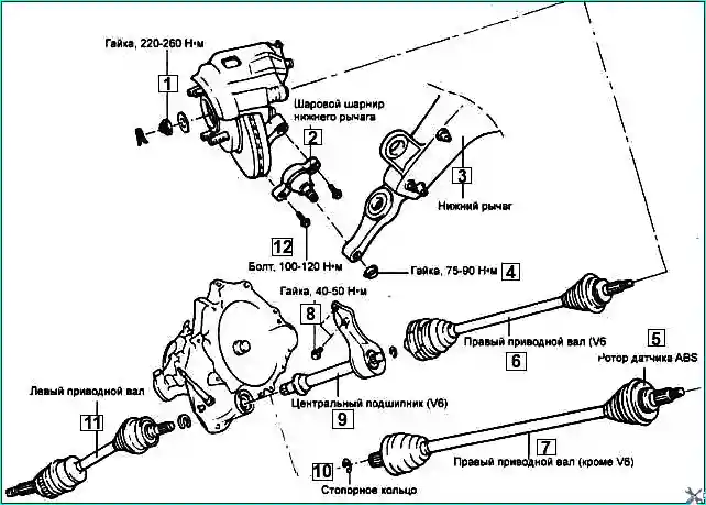
Tighten the following elements to the tightening torques:
Drive shaft mounting nut: 200–260 Nm
Lower arm ball joint to joint: 100–120 Nm

")
")
")
")
")
")
")
")