
We conduct automatic transmission checks to determine the malfunction of transmission components
Checking the transmission switch conductivity
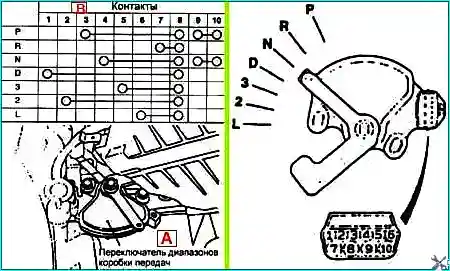
Disconnect the connector and use a tester to check the conductivity of the gearbox range switch at different positions of the selector lever
Checking the conductivity of the sport mode switch (F4A42–2 2.0 and 2.5 l)
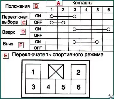
Disconnect the connector and check the conductivity of the sport mode switch
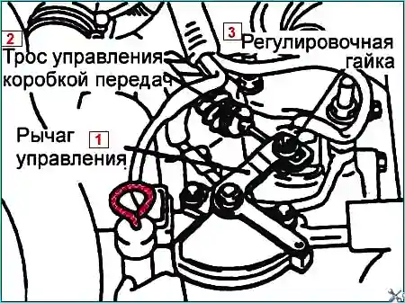
Gearbox range switch and control cable adjustment
Set the selector lever to the neutral position "N"
On the gearbox side, loosen the nut securing the control cable to the lever to release the cable and the control lever
Set the selector lever to neutral position
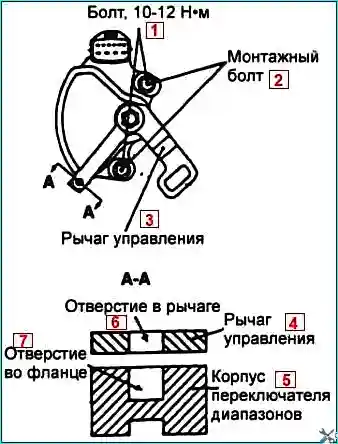
Loosen the mounting bolts of the gearbox range switch housing
Then turn the gearbox range switch housing so that the hole on the end of the control lever and the hole in the protrusion of the gearbox range switch housing are aligned
Tighten the mounting bolts of the gearbox range switch housing to the tightening torque specified in the specification
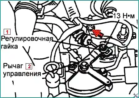
Gently press the gearbox control cable in the direction of the arrow and tighten the adjusting nut
Check that the selector lever is in the "N" position
Check the operation and functioning of the switch for each position of the selector lever
Checking the components of the automatic transmission
- Checking the throttle position sensor
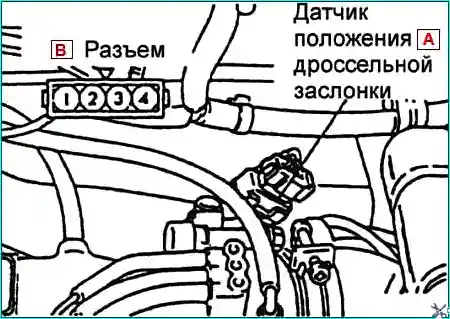
Disconnect the connector from the throttle position sensor.
Measure the resistance between terminals 1 and 4 of the connector on the throttle position sensor side.
Resistance: 3.5 - 6.5 kΩ
Measure the resistance between terminals 2 and 4 of the connector on the throttle position sensor side.
Normal condition:
If the throttle valve opens slowly from the rest position to the fully open position, the resistance should change smoothly in accordance with the throttle opening angle.
If the resistance is different or does not change smoothly, replace the throttle position sensor.
- Checking the oil temperature sensor
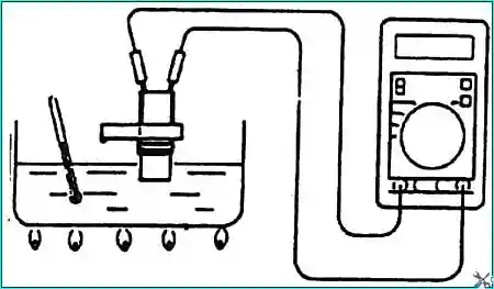
Remove the oil temperature sensor.
Measure the resistance between terminals 1 and 2 of the sensor connector.
Resistance:
- 16.7–20.5 kOhm at 0° C
- 0.57–0.69 kOhm at 100° C
- Checking the vehicle speed sensor
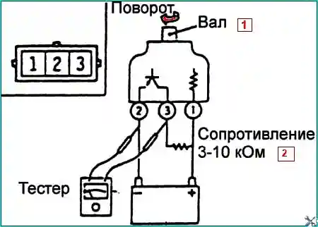
Remove the vehicle speed sensor and connect a 3-10 kOhm resistor as shown in the figure.
Turn the shaft of the vehicle speed sensor and check that there is voltage between terminals 2 and 3 (1 revolution = 4 pulses).
- Checking the A / T control relay
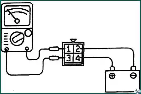
Remove the A / T control relay.
With jumpers Connect terminal (2) of the A/T control relay to the negative (–) terminal of the battery and terminal (4) of the control relay to the positive (+) terminal of the battery.
Check for continuity between terminal (1) and terminal (3) of the A/T control relay when jumper wires are connected and disconnected from the battery.
There should be continuity between the relay terminals when jumper wires are connected.
There should be no continuity between the relay terminals when jumper wires are disconnected.
If the test results are negative, replace the relay.
- Checking the Solenoid Valve
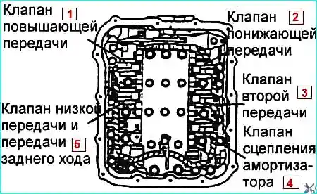
Remove the valve body cover.
Disconnect the connectors from each solenoid valve.

Measure the resistance between terminals 1 and 2 of each solenoid valve.
Resistance:
Shock Absorber Clutch Solenoid Valve: 2.7–3.4 ohms at 20°C
Low and reverse solenoid valve: 2.7–3.4 ohms at 20°C
2nd gear solenoid valve: 2.7–3.4 ohms at 20°C
Downshift solenoid valve: 2.7–3.4 ohms at 20°C
Upshift solenoid valve: 2.7–3.4 ohms at 20°C
If the resistance of the valve is different, replace the solenoid valve.
Testing the interaction of the automatic transmission and engine with the vehicle stationary (stall test)
The test is performed to determine the maximum engine speed when the selector lever is in the D or R position, and to check the operation of the torque converter, starter and one-way clutch, as well as the characteristics of the clutches and brakes.
No one should stand in front or behind the vehicle while testing.
Before testing, check the levels of all operating fluids and, if necessary, top them up to normal.
- - The transmission fluid temperature should be between 80 and 100°C.
- - The coolant temperature should be between 80 and 100°C.
- - Place chocks under the rear wheels.
- - Apply the parking brake and press the brake pedal.
- - Start the engine.
- - Move the selector lever to position D. Press the brake pedal all the way down with your left foot and gently press the accelerator pedal with your right foot.
When the engine speed no longer increases, read the tachometer and release accelerator pedal.
To avoid damage to the transmission, test for 8 seconds.
If more than one test is required with the engine running, move the selector lever to position N and let the engine run at idle speed until the transmission fluid cools.
Running the engine at idle speed cools the transmission fluid and prevents its properties from deteriorating.
Engine speed for testing the combined operation of the automatic transmission and engine on a stationary vehicle ( stall test ): 2000–2900 min¹
(6) Perform the test in the same way with the selector lever in position R.
Engine speed for testing the combined operation of the automatic transmission and engine on a stationary vehicle ( stall test ): 2000–2900 min¹
- Engine speed is above specification in position D and R.
- - Low line pressure.
- - Slipping of brake bands in low and reverse gear.
- Engine speed is above specification only in position D.
- - Slipping of underdrive clutch.
- If engine speed is above specification only in position R.
- - Slipping of reverse clutch.
- If engine speed is below specification in position D and R.
- - Damage to the torque converter.
- - Insufficient engine power

")
")
")
")
")
")
")
")