
Removing the timing belt drive
Disconnect the negative cable from the battery.
Remove the engine cover (A).

Remove the front right wheel.
Remove the side cover.

Set cylinder #1 piston to TDC/compression.
Drain engine oil, then install jack to oil pan.
NOTE:
Install wooden block - between jack and oil pan.

Remove the engine mount bracket.

Remove the accessory drive belt.
Remove the pulley and drive belt tensioner. (Tensioner pulley bolt with left-hand thread)

Remove the water pump pulley (A), crankshaft pulley (B) and engine mount bracket (C).

Disconnect the OSU (A) cable connector.

Disconnect the ventilation hose.

Disconnect the ignition coil connector (A) and the RSU hose (B).

Remove the ignition coils.

Remove the cylinder head cover

Unscrew the lower bolts of the air conditioning compressor

Remove the compressor mounting bracket.

Unscrew the mounting bolts and remove the oil pan.
Do not damage the contact surfaces of the cylinder block and oil pan.

Remove the cover timing chain cover (A), carefully aligning it between the head and the cylinder block.
Do not damage the contact surfaces of the cylinder block, cylinder head and timing chain cover.
The crankshaft key should be flush with the mating surface of the main bearing cap.
As a result, the piston of cylinder No. 1 will be at TDC, compression stroke.

Install the locking pin after moving the rod tensioner inside the housing, as shown in the figure.

Remove the chain tensioner (A) and the chain tensioner lever (B)
Remove the timing chain.

Remove the chain guide (A).
Remove the timing chain oil sprayer (A).

Remove the crankshaft timing chain sprocket (B).
Remove the balance shaft chain
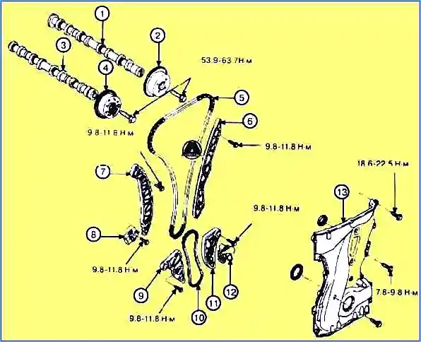
Installing the timing drive
Install the sprocket crankshaft drive chain.
Install the chain oil sprayer (A) (see figure above). Tightening torque 7.8 - 9.8 Nm.
Install the crankshaft so that the key is flush with the mating surface of the main bearing cap.
Locate the intake and exhaust camshafts so that the TDC mark on the intake and exhaust sprockets are flush with the top surface of the cylinder head.
As a result, the position of the piston of cylinder No. 1 will be at TDC, compression stroke.

Install the timing chain guide (A). Tightening torque: 9.8 - 11.8 Nm.
Install the timing chain.
To install the chain without slack between each shaft (camshaft and crankshaft), follow the procedure:
Crankshaft sprocket (A) -> timing chain guide (B) -> CVVT intake sprocket assembly (C) -> CCVT exhaust sprocket assembly (D).

The marks on each sprocket must match the timing chain marks (colored) when installing the chain.

Install the chain tensioner lever (B). Tightening torque 9.8 -11.8 Nm.
Install the timing chain automatic tensioner (A) and remove the installed stud. Tightening torque 9.8 - 11.8 Nm.

After turning the crankshaft 2 turns clockwise (front view), put marks as shown in the figure.
Install the timing chain cover.

Using a gasket clip, remove the old material from the surface of the gaskets.
The areas where the sealant is applied to the chain cover, cylinder head, cylinder block and ladder frame should not come into contact with oil and ETC.
Before assembling the chain cover, liquid sealant should be applied to the gap between the head and the cylinder block.
The parts should be assembled within 5 minutes after applying the sealant. The width of the strip is 3 mm.
The cylinder block dowel pin and the timing chain cover holes should be used according to the assembly order of the chain cover to be in the correct position. Tightening torque: M6: 7.8 – 9.8 Nm, M8: 18.6 – 22.5 Nm.

Burning and blowing the timing chain cover should be done no later than 30 minutes after assembly.
Install the oil pan

Using a gasket scraper, remove the old material from the surface of the gaskets.
Before assembling the oil pan, liquid sealant should be applied between the joint surfaces cylinder block and sump.
When applying sealant, do not allow sealant to get inside the oil pan.
After assembly, wait at least 30 minutes before adding oil to the engine.

Install the compressor mounting bracket (A). Tightening torque: 19.6 - 23.5 Nm

Tighten the lower compressor mounting bolts. Tightening torque: 19.6 – 24.5 Nm.

Install the cylinder head cover cylinders.
Excess sealant squeezed out on the upper surface of the timing chain cover and cylinder head must be removed before installing the cylinder head cover.
After applying the sealant, assembly must be completed within 5 minutes. The strip width is 2.5 mm.
Burning and blowing the cylinder head must be carried out no later than 30 minutes after assembly.

Tighten the cylinder head cover bolts as follows:
- Step 1: torque tightening torque 3.9 – 5.95 Nm
- Step 2: tightening torque 7.8 – 9.8 Nm.
Do not reuse the cylinder head gasket

Install the ignition coils (A). Tightening torque: 3.9 – 5.9 Nm.

Connect the ignition coil connector (A) and the hose

Connect the ventilation hose (A).

Connect the exhaust valve connector (A).
Install the engine support bracket (C). Tightening torque: M10: 39.2 - 44.1 Nm, M8: 19.6 - 24.5 Nm.

Install the crankshaft pulley (B). Tightening torque: 166.6 - 176.4 Nm.
Use a flywheel locking tool to install the crankshaft pulley bolt, then remove the starter.
Install the water pump pulley (A). Tightening torque: 7.9 - 9.8 Nm.

Install the drive tensioner (B). Tightening torque: 63.7 Nm.
NOTE:
The tensioner pulley bolt has a left-hand thread.
Install the roller (A). Tightening torque: 53.9 - 63.7 Nm.
Install the drive belt (A) as follows:

Crankshaft pulley ->A/C pulley ->Alternator pulley ->Roller pulley ->N/C pulley Power steering pump -> roller pulley -> water pump pulley -> tensioner pulley.
Rotate the auto tensioner lever clockwise, moving the auto tensioner bolt with a wrench.

Install the engine mount bracket (A). Tightening torque: 63.7 - 83.4 Nm.
Install the side cover. Tightening torque: 8.8 - 10.8 Nm.
Install the front right wheel. Tightening torque: 88.3 – 107.9 Nm.

Install the engine cover (A).
Connect the negative cable to the battery.
Checking the technical condition of the timing belt components
Sprockets, hydraulic tensioner, chain guide and tensioner lever
Check the teeth of the camshaft drive sprockets and crankshaft for increased wear, chips and breakages. If necessary, replace the sprockets with new ones
Check the contact surface with the chain at the tensioner lever and guide for increased wear and damage. If necessary, replace with new ones.
Check the stroke of the hydraulic tensioner plunger and the smoothness of its movement.
If any defects are found, replace the tensioner assembly.
Auxiliary equipment drive belt and pulleys
Check the intermediate pulley for contamination with oil products, as well as for increased wear and damage.
If defects are found, replace with a new one.
Check the drive belt for increased wear. If necessary, replace with a new one.
Check the pulleys for vibrations during rotation. If necessary, replace the pulley with a new one.

")
")
")
")
")
")
")
")