Most of the vehicle's electrical power circuits are protected by fuses
Headlights, fan motors, fuel pump and other powerful current consumers are connected via relay
Fuses and relays are installed in mounting blocks located under the hood and in the passenger compartment
The purpose of fuses, fuses and relays is indicated below
Fuses and relays of the mounting block in the engine compartment
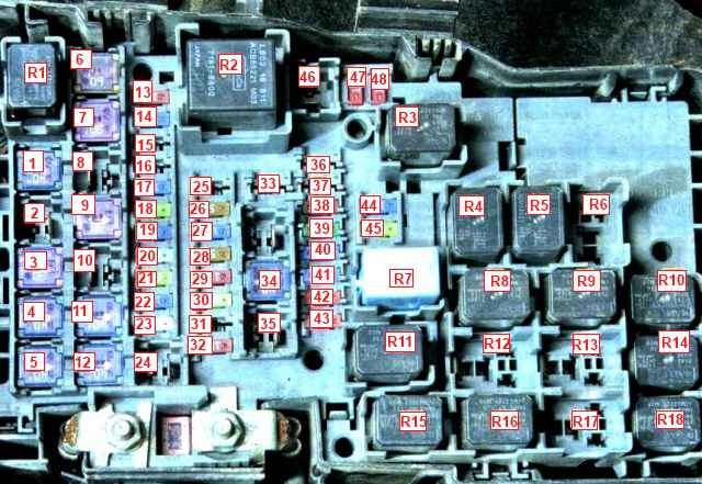
- R1 - A/C compressor relay
- R2 - Main relay
- R3 - low beam relay
- R4 - starter relay
- R5 - horn relay
- R6 - rear light relay
- R7 - fuel pump relay
- R8 - electrical outlet relay
- R9 - low speed relay for engine cooling fan
- R10 - low speed relay for engine cooling fan
- R11 - high beam relay
- R12 - high speed relay for engine cooling fan
- R13 - high speed relay for engine cooling fan
- R14 - rear window defroster relay
- R15 - starter relay
- R16 - front fog lamp relay
- R18 - heater relay
Fuses No. - A - color - protected circuits
- 1- 40 - green - heater;
- 2 - 40 - green - PTC;
- 3 - 30 - pink - power windows;
- 4 - 40 - green - engine start system;
- 5 - 40 - green - protection of electrical circuits;
- 6 - 60 - yellow - anti-lock braking system;
- 7 - 30 - pink - electric fan of the engine cooling system;
- 8 - 20 - yellow - aux heater
- 9 - 30 - pink - electric fan of the engine cooling system;
- 10 - 50 - red - PRECRASH;
- 11 - 40 - green - rear window defroster;
- 12 - 40 - green - electric seat adjustment;
- 13 - 10 - red - air conditioning system;
- 14 - 15 - blue - electrical outlet;
- 15, 16 - diesel
- 17 - 15 - blue - electric sunroof;
- 18 - 20 - yellow - heated seats;
- 19 - 15 - blue - cabin equipment control unit;
- 20 - 25 - white - audio system;
- 21 - 20 - yellow - headlight washer;
- 22 - 15 - blue - fog lights;
- 23 - 25 - white - electric door lock;
- 26 - 5 - orange - brake lights;
- 27 - 15 - blue - beep;
- 28 - 5 - orange - engine management system;
- 29 - 10 - red - direction indicators and hazard warning lights;
- 31 - 10 - red - electronic steering lock;
- 32 - 10 - red - engine management system;
- 34 - 40 - green - protection of electrical circuits;
- 38 - 7.5 - brown - electrically heated mirrors;
- 39 - 30 - pink - anti-lock braking system and stabilization system;
- 40 - 15 - blue - right low beam headlight;
- 41 - 15 - blue - left low beam headlight;
- 42 - 10 - red - right high beam headlight bulb;
- 43 - 10 - red - left headlight high beam;
- 44 - 15 - blue - nozzles;
- 45 - 20 - yellow - fuel pump;
- 47 - 10 - red - engine management system;
- 48 - 10 - red - injectors
Fuses of the mounting block in the car interior
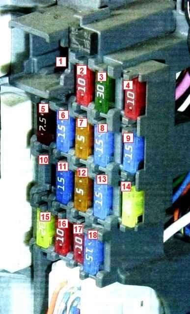
- 1 - 30 - pink - power windows;
- 2 - 10 - red - adaptive lighting system;
- 3 - 30 - green - central door lock;
- 4, 9, 10, 14 - reserve;
- 5 - 7.5 - brown - instrument panel lighting;
- 6 - 15 - blue - cigarette lighter;
- 7 - 5 - orange - electric side mirrors;
- 8 - 15 - blue - electrical outlet;
- 11 - 15 - blue - engine management system;
- 12 - 5 - orange - security system;
- 13 - 15 - blue - dashboard;
- 15 - 20 - yellow - wiper and washer;
- 16 - 10 - red - air conditioner compressor;
- 17 - 10 - red - tailgate wiper and washer;
- 18 - 15 - blue interior lights
To access the mounting block located in the salon:
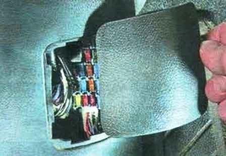
We press the latch and, moving the cover to the side, remove it from the end of the lower trim of the front door pillar
There is a fuse diagram on the inside of the cover, and an arrow on the cover indicates the direction of movement of the car
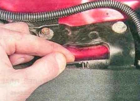
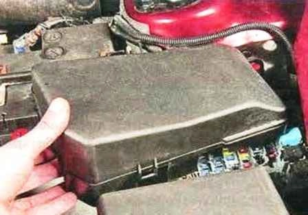
In the engine compartment, to gain access to the mounting block, press the cover latch and remove the cover
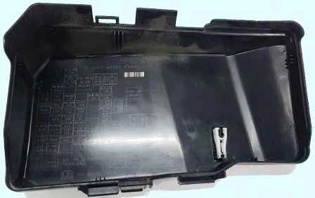
There is a fuse diagram on the inside of the cover, and an arrow on the cover indicates the direction of movement of the car
Before you replace a blown fuse or relay, you need to find out the cause of the blown and eliminate it
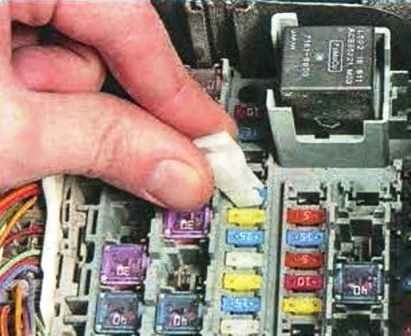
Remove the fuse with tweezers
We install a fuse of the same rating as the removed one into the contact socket
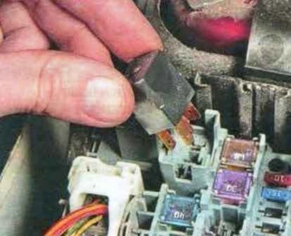
If it is necessary to replace the relay, remove it from the mounting block, rocking it from side to side
Installing a new relay


