
Depending on the vehicle equipment, the heating system can be equipped with an air conditioning system, but there are options without air conditioning
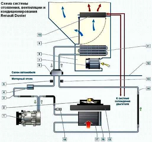
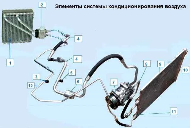
Scheme of the heating and air conditioning system: 1 - compressor, 2 - fan of the engine cooling system; 3 - low pressure pipeline; 4 - damper; 5 - valve for charging and discharging refrigerant in the low pressure pipeline; 6 - gearbox; 7 - heater fan; 8 - heater housing; 9 - damper of the temperature controller; 10 - heater radiator; 11 - evaporator; 12 - front panel; 13 - valve for charging and discharging refrigerant in the high pressure pipeline; 14 - high pressure pipeline; 15 - radiator of the engine cooling system; 16 - receiver dryer; 17 - air conditioner; 18 - refrigerant pressure sensor
The heating and ventilation system includes: a heater, a heater fan, air ducts and deflectors.
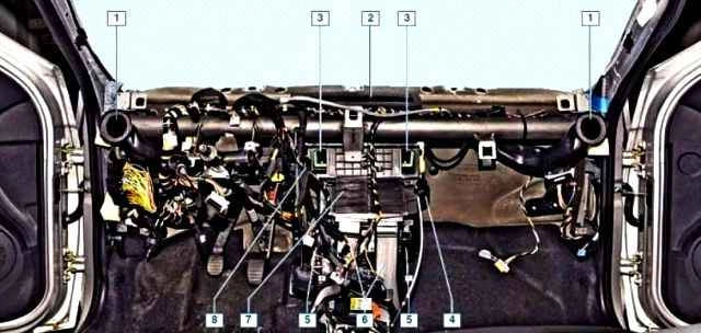
The location of the heater and air ducts of the air conditioning and heating system (shown with the instrument panel removed): 1 - air duct to the side deflector; 2 - air duct to the windscreen blower grille; 3 - air duct to the central deflectors; 4 - heater fan motor; 5 - air ducts to the feet of the front passengers; 6 - air ducts to the legs of the rear seat passenger; 7 - heater; 8 - additional fan resistor
Air ducts supply air from the heater to the windshield and side window vents, to the central and side instrument panel vents, as well as to the ventilation openings in the heater casing to supply air to the driver's and passengers' feet.
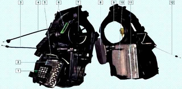
Heater elements (for clarity, shown on the disassembled heater body): 1 - additional interior electric heater; 2 - heater radiator; 3 - temperature controller damper rod, 4 - recirculation damper rod, 5 - temperature controller damper; 6 - distribution damper; 7 - recirculation damper; 8 - sealant; 9 - fan socket; 10 - cabin filter; 11 - air conditioner evaporator; 12 - control valve rod
The system is controlled by turning the handles located on the heating, ventilation and air conditioning control unit.
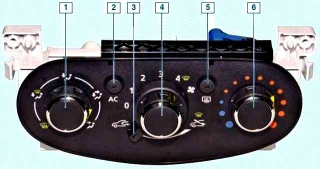
Heating, ventilation and air conditioning control unit: 1 - air flow distribution regulator; 2 - air conditioner switch; 3 - control lever for air recirculation mode; 4 - fan operation mode switch; 5 - switch for heating the glass of the tailgate; 6 - air temperature controller
The control unit is installed on the instrument panel console.
The heater is installed under the instrument panel in the center, the air ducts are fixed under the cross member of the instrument panel.
The heater fan is installed in the heater housing.
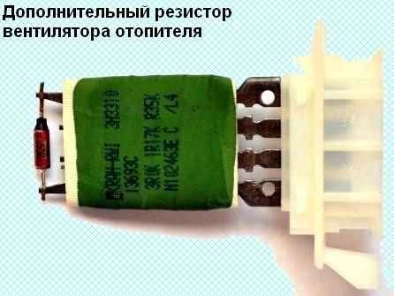
Auxiliary fan resistor, A/C evaporator (on a vehicle with A/C), distribution flaps that control airflow to specific areas, and a heater core connected by hoses to the engine cooling system.
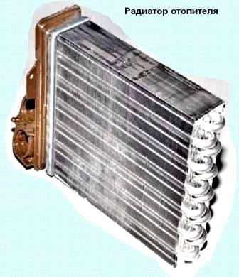
Coolant constantly circulates through the radiator.
Depending on the position of the damper associated with the temperature controller, outside air can pass through the heater core or bypass it.
In intermediate damper positions, part of the air passes through the radiator, and the rest bypasses the radiator.
In the extreme positions of the damper, all air passes through the radiator or bypasses it.
When the car is moving, air enters the heater through the holes located on the left and right windshield linings.
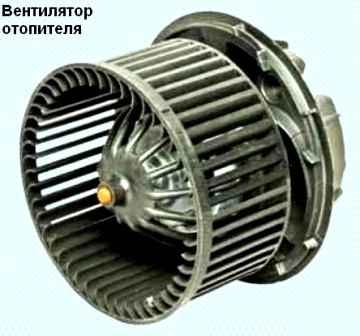
To increase the air supply to the passenger compartment while the car is moving, as well as in the parking lot, the heater fan is used.
The airflow rate is determined by the fan speed.
The fan motor can rotate at four different speeds depending on the connection of the additional resistor.
The air flow in the cabin is controlled by the air flow distribution regulator, which is connected to the dampers by rods.
By turning the dampers, the regulator directs air flows through the air ducts to the central and side vents, to the lower ventilation openings in the heater casing, as well as to the windscreen grilles located in the instrument panel.

The air exits the passenger compartment through the slots in the trunk upholstery and then out through the valves installed behind the right side of the rear bumper.
To accelerate the warm-up of the passenger compartment and prevent the entry of outside air into the passenger compartment (when the car is driving on smoky or dusty sections of the road), an air recirculation system is used.
When the air recirculation mode is turned on, the recirculation damper blocks the access of outside air to the vehicle interior, while the air in the vehicle interior begins to circulate in a closed circuit without exchanging with outside air.
Some cars are equipped with an air conditioning system.
The air conditioning system is designed to reduce the temperature and humidity in the cabin.
The air conditioner is turned on by pressing the air conditioner switch button located in the heating, ventilation and air conditioning control unit, while the heater fan must be turned on.
When the air conditioner is turned on, the indicator located in the air conditioner switch button lights up.
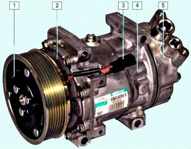
Air conditioning compressor: 1 - pulley with electromagnetic clutch; 2 - front cover; 3 - output of the wires of the electromagnetic clutch; 4 - body; 5 - back cover
The A/C compressor is mounted on the engine bracket at the front, under the generator.
The compressor compresses the refrigerant coming to it from the evaporator, which is in a vapor state at a low pressure of 0.5-2.0 bar.
At the outlet of the compressor, the refrigerant vapor pressure increases, and the temperature reaches 80-100˚ C.
The air conditioning compressor is driven by a V-ribbed belt from the accessory drive pulley.
A frictional electromagnetic clutch is built into the compressor pulley, which connects and disconnects the compressor shaft with the pulley according to the signals from the engine control unit.
From the compressor, the refrigerant vapor enters the condenser located in front of the radiator of the engine cooling system.
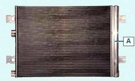
When the condenser plates are blown with air flow generated while the car is moving, as well as with the help of a cooling system fan, the refrigerant under high pressure (15.0-20.0 bar) changes from a gaseous state to a liquid state.
A receiver-drier is built into the right side of the condenser.
The receiver-drier is also equipped with a filter to clean the refrigerant from impurities.
From the condenser, the refrigerant enters the reducer, which is a throttle valve, at the outlet of which the pressure and temperature refrigerant drops sharply (up to 1.0 bar and down to -7˚ C).
As a result of this, the refrigerant enters the evaporator located in the heater body.
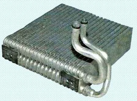
The flow of air passing through the heater housing through the evaporator under the influence of the heater fan causes the refrigerant to evaporate.
At the same time, the air, giving off heat to the refrigerant in the evaporator, becomes colder.
From the evaporator, the refrigerant is sucked in again by the compressor, and the work cycle is repeated.
Valves are installed on the high and low pressure pipelines for charging and discharging refrigerant from the air conditioning system.
A refrigerant pressure sensor is installed on the pipeline between the compressor and the condenser.
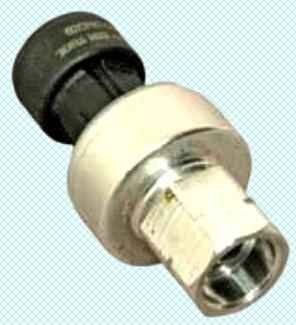
The sensor sends a signal to the engine control unit, which controls the engine cooling fan depending on the coolant pressure and vehicle speed.
In addition, according to the pressure sensor signals, the engine control unit turns off the air conditioning compressor when the refrigerant pressure in the system drops to 2.0 bar and when the pressure rises to 27.0 bar.
A shut-off valve is installed in the pipe fitting under the pressure sensor, which closes when the sensor is unscrewed.
Therefore, when replacing the pressure sensor, there is no refrigerant leakage from the air conditioning system.
The refrigerant in the air conditioning system is under high pressure.
During work related to depressurization of the air conditioning system, avoid contact of the refrigerant with the eyes, skin and respiratory tract.
Any work with refrigerant should be carried out only in a ventilated area.
When charging the air conditioning system, use only materials recommended by the manufacturer.
It is forbidden to carry out welding or soldering work on the components of the air conditioning system.
Work on maintenance and repair of the air conditioning system should be carried out at specialized service stations.
Special equipment is used to search for leaks in the system, and a special contrast agent will need to be injected into the system.
After removing the refrigerant from the system, be sure to evacuate the air to remove residual moisture.
Special oil must be added to the system before filling.

")
")
")
")
")
")
")
")