Fuses in a car protect most circuits.
The fuse rating is calculated taking into account the load of the electrical circuit
If you install a fuse of a larger rating, then under significant loads, the circuit elements (wiring and parts of the electrical circuit diagram) will fail
If you install a fuse of a smaller rating than it is calculated according to the scheme, then the fuse will fail even with minor loads. Therefore, you need to install fuses of the appropriate rating.
Consumers with high power are connected via relays
Carry out any work on the electrical equipment of the car only with the battery disconnected.
Disconnect or connect the battery only when the ignition is off.
When checking the circuits of electrical equipment, it is forbidden to short the wires to ground (check the health of the circuits "for a spark"), as this can lead to failure of electrical equipment elements.
It is forbidden to use fuses that are not provided for by the design of the car or designed for a higher current, and also to use wire instead of fuses.
When replacing fuses, do not use screwdrivers, as this can lead to a short circuit in electrical circuits.
It is forbidden to disconnect the battery while the engine is running in order to avoid damage to the voltage regulator and elements of the car's electronic equipment.
When carrying out electric welding work on a car, it is necessary to disconnect the wires from the battery terminals, the generator and the electronic engine control unit.
Fuse boxes are located under the hood and in the passenger compartment
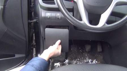
To access the mounting block in the car interior, pry the notch in the decorative cover of the mounting block with your fingers
Remove the cover from the instrument panel
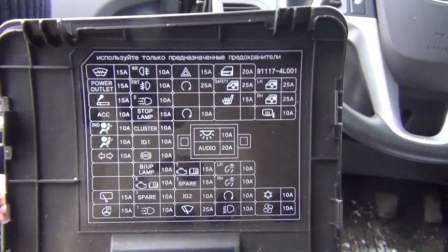
The fuse layout is printed on the inside of the decorative cover
Before you replace a blown fuse, you need to find out the cause of its blown and eliminate the cause.
We look at the table which circuit this fuse protects, check this circuit, fix the malfunction, and only after that we install a new fuse of the same rating.
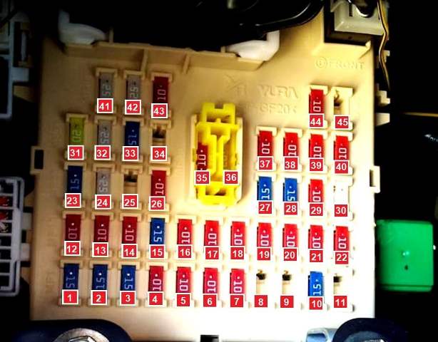
The fuse box in the passenger compartment is located in the instrument panel on the left side under the decorative cover
The purpose of the fuses is indicated on the block and in the figure
The circle of troubleshooting is usually narrowed by gradually identifying and eliminating normally functioning elements of the same circuit.
If several elements or circuits fail at the same time, the most likely cause of the failure is a blown fuse or a broken contact with the "ground" (different circuits in many cases can be closed to one fuse or ground terminal).
Electrical equipment failures are often due to the simplest causes, such as corrosion of connector contacts, fuse failure, fuse blown, or relay damage.
Visually check the condition of all fuses, wiring, and connectors in the circuit before proceeding to a more detailed check of the health of its components.
One of the methods for finding a short circuit is to remove the fuse and connect a probe lamp or voltmeter instead.
There must be no voltage in the circuit. Pull the wiring while watching the probe lamp.
If the lamp starts flashing, there is a short to ground somewhere in this wiring harness, possibly caused by chafing of the wire insulation.
A similar test can be carried out for each of the components of the electrical circuit by turning on the appropriate switches.
Circuits protected by fuses in the mounting block in the saloon
No./current "A" - Protected circuit/color
- 1/15 - Heated windscreen/blue
- 2/15 - Socket for connecting an additional equipment/blue
- 3/15 - Cigarette lighter/blue
- 4/10 - Ignition switch/red
- 5/10 - Front airbag deactivation indicator/red
- 6/10 - Airbag/Red
- 7/10 - Hazard switch/red
- 8, 9, 11, 25, 34, 45 - Reserved
- 10/15 - Windshield wiper and washer selector lever/blue
- 12/10 - Rear fog light/red
- 13/10 - Front fog lights/red
- 14/10 - Battery saving relay (dimensions turn off after the key is removed from the ignition lock) / red
- 15/15 - Stop lights/blue
- 16/10 - Instrument cluster/red
- 17/10 - Security Control Module/Red
- 18/10 - ABS module/red
- 19/10 - Reversing light switch/red
- 20/10 - Immobilizer/red
- 21/10 - Left Headlight/Red
- 22/10 - Daytime running lights/red
- 23/15 - Hazard switch/blue
- 24/25 - Electronic key control module/grey
- 26/10 - Engine start/stop button/red
- 27/15 - Vehicle speed sensor/blue
- 28/15 - Ignition coil/blue
- 29/10 - Power windows, sunroof/red
- 30/25 - Windshield wiper/grey
- 31/20 - Door lock control unit/yellow
- 32/25 - Power window lock/grey
- 33/15 - Heated front seats/blue
- 35/10 - Interior lighting, air conditioning/red
- 36/20 - Audio system/yellow
- 37/10 - Left Rear Light, License Plate Lights, Left Headlight/Red
- 38/10 - Right rear light, right headlight/red
- 39/10 - Starter relay, anti-theft alarm/red
- 40/10 - Right Headlight/Red
- 41/25 - Power window control unit, left rear power window switch/grey
- 42/25 - Power Window Control Module, Right Rear Power Window Switch/Grey
- 43/10 - Heated exterior mirrors/red
- 44/10 - Conditioner/Red
Please note that, depending on the configuration, fuses may be added or there may be no fuses.
Under the hood of the car, the fuse box is located on the left side in the direction of the car and is closed by a cover.
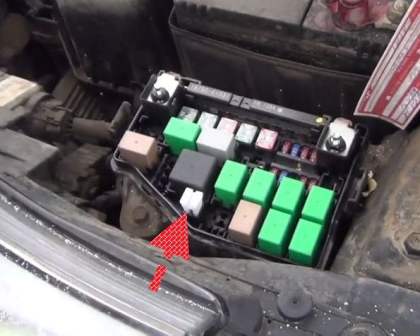
To remove the fuses, there are tweezers in the socket of the mounting block under the hood
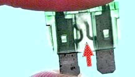
It usually looks like a fuse with a blown jumper
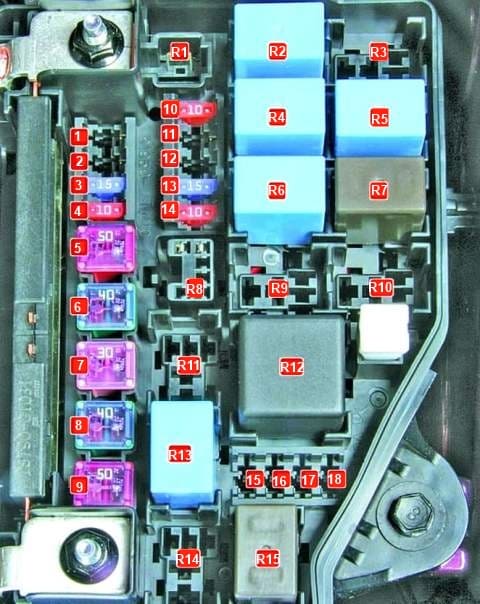
Assignment of the fuses in the mounting block under the hood
No./A - Protected circuit/fuse color
- 1, 2, 11, 12, 18 - reserve
- 3/15 - Fuel Module/Blue
- 4/10 - Beep/red
- 5/50 - Power windows, hazard switch, central locking/red
- 6/40 - Heating control unit/blue
- 7/30 - ECM/Red
- 8/40 - Ignition lock, engine start/stop button/blue
- 9/50 - Ignition lock, engine start/stop button/red
- 10/10 - Conditioner/Red
- 13/15 - Power system/blue
- 14/10 - Camshaft position sensor, oxygen sensor/red
- 15/10 - ECM/Red
- 17/10 - Cluster, rear lights/red
Assignment of the relay in the engine compartment
No. - Purpose
- R1, R14 - reserve
- R2 - Horn relay
- R3 - Ignition lock relay, engine start and stop buttons
- R4 - A/C relay
- R5 - Ignition Interlock Switch Relay
- R6 - Fan relay (low speed)
- R7 - Fan relay (high speed)
- R8 - Diagnostic socket relay
- R9 - Ignition lock relay
- R10 - Ignition lock relay, engine start and stop buttons
- R11 - emergency brake warning
- R12 - ECM relay
- R13 - Fuel pump relay
- R15 - Radiator fan relay
Fusible links in the main fuse
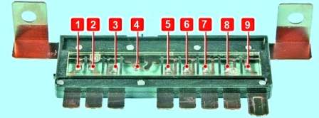
Assignment of fusible links
Number/Ampere - protected circuit:
- 1/50 - Tail light relay;
- 2, 3, 9 - reserve;
- 4/125 - Generator;
- 5/40 - ABS module, diagnostic connector;
- 6/40 - ABS module;
- 7/40 - Rear window heating relay;
- 8/40 - Fan relay
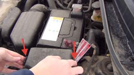
To access the fuses of the mounting block in the engine compartment, press the cover latches
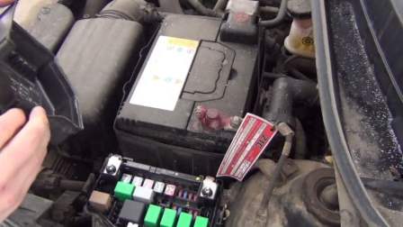
Remove the cover
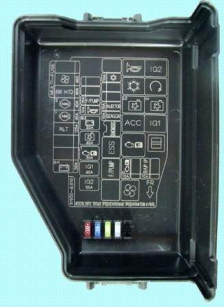
The inside of the cover has a fuse diagram and spare fuses installed
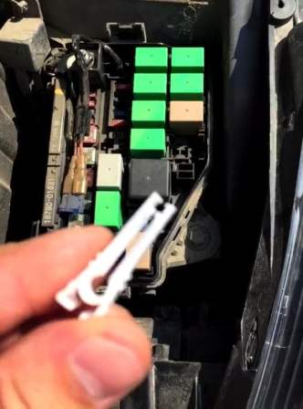
We use special tweezers to replace fuses
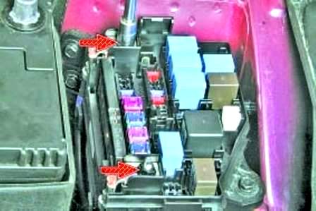
To replace the main fuse, you need to unscrew the two nuts and remove the wire lugs from the studs of the mounting block
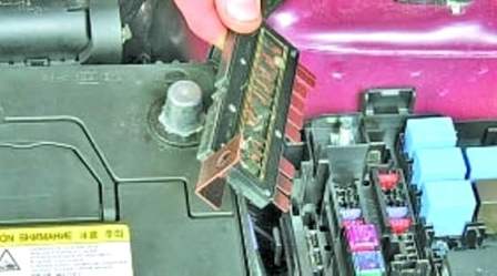
Pry off with a screwdriver and remove the main fuse
We examine main fuse for blown jumpers and melting
Install the main fuse in reverse order
Removing and installing the mounting block of fuses in the passenger compartment
Disconnect the negative battery terminal
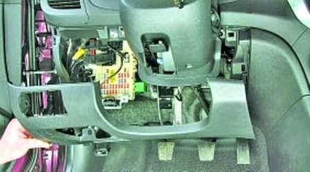
Remove the lower lining of the instrument panel
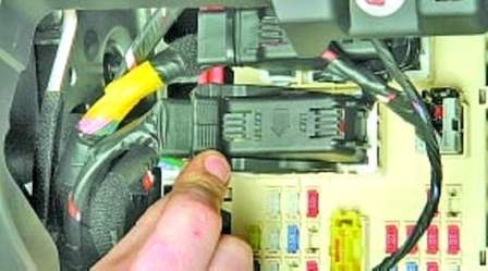
Flip back the fixing bracket
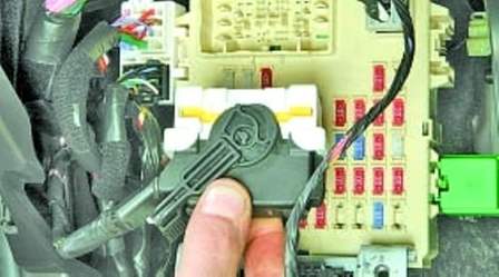
Disconnect the wiring block from the mounting block
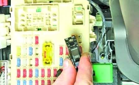
Also disconnect the upper block of the wiring harness
We press the latch and disconnect the side block of the wiring harness
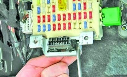
Pry off with a screwdriver and remove the diagnostic connector from the mounting bracket of the mounting block
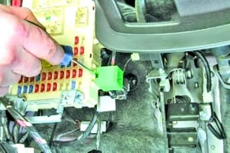
Press the relay retainer
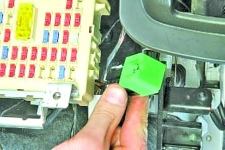
Disconnect the relay from the right wall of the mounting block
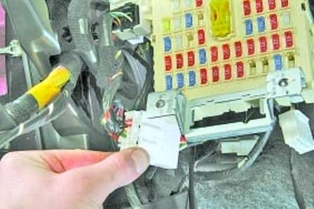
We also disconnect the lower block of the wiring harness from the left wall of the mounting block
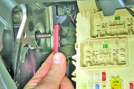
Disconnect the upper block of wires from the left wall of the mounting block
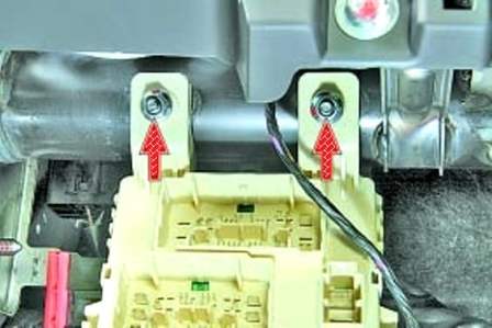
Unscrew the two nuts securing the mounting block
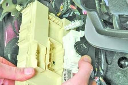
We take the mounting block to the side and disconnect the three rear wire blocks
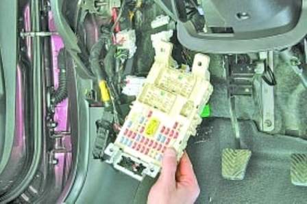
Remove the fuse mounting block


