

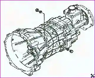
In the previous article we examined the disassembly of the 038М gearbox. In this article we examine the assembly of the 038М gearbox.
Materials used and precautions:
- For sealing the mounting surfaces, use sealant and apply a bead of 1.2 mm diameter.
- Install the parts no later than ten minutes after applying the sealant.
- To lubricate the input shaft splines and the release fork support head, use molybdenum-based grease.
- Tighten the mounting bolts to the recommended torque; for multiple bolts, follow the diagonal sequence.
- Use new sealing washers when installing the plugs.
- When seating the rear case, a few light blows with a plastic mallet are permitted.
Step-by-step assembly
1. Preparation and application of sealant to the transmission case and intermediate plate
Clean the mounting surfaces of the transmission case and the intermediate plate. Apply a bead of sealant of 1.2 mm diameter to the mounting surface of the transmission case and the intermediate plate.
Note: install the transmission case no later than ten minutes after applying the sealant.

2. Installation of the transmission case
Install the transmission case onto the intermediate plate of the gearbox.
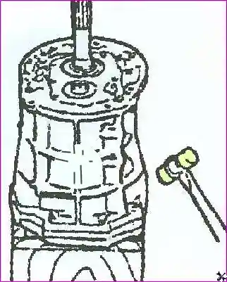
3. Installation of the bearing snap rings
Install the input shaft bearing snap ring and the front intermediate shaft bearing snap ring.
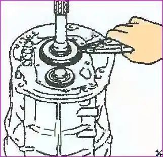
4. Application of sealant to the case and front cover
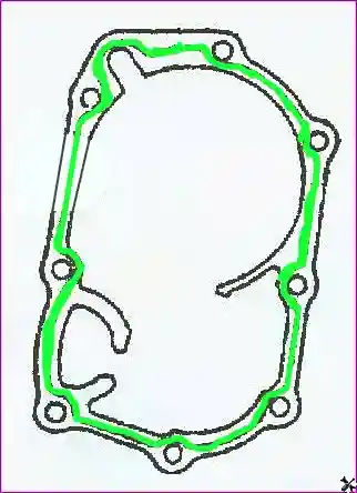
Clean the mounting surfaces of the transmission case and the front cover. Apply a bead of sealant of 1.2 mm diameter to the mounting surface of the transmission case and the front cover.
Note: install the front cover no later than ten minutes after applying the sealant.
5. Installation of the front cover
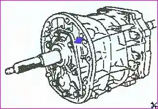
Install the front cover and secure it with eight bolts. Tighten the bolts to the recommended torque.
Tightening torque: 11.55–21.45 N·m.
Note: tighten the bolts in a diagonal sequence.
6. Installation of the shift shaft and shift block
Install the shift shaft and the gear shift block onto the rear case of the gearbox.

7. Application of sealant to the rear case
Clean the mounting surface of the rear case. Apply a bead of sealant of 1.2 mm diameter to the mounting surface of the rear case.
Note: install the rear case no later than ten minutes after applying the sealant.

8. Installation of the rear case
Install the rear case of the gearbox.
Note: apply a few light blows to the rear case using a plastic mallet.
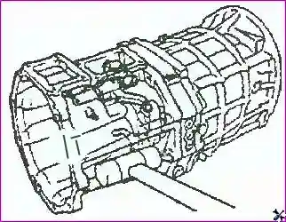
9. Tightening the rear case mounting bolt
Screw in and tighten the mounting bolt to the recommended torque.
Tightening torque: 25.9–48.1 N·m.

10. Tightening the shift block bolt
Screw in and tighten to the recommended torque the bolt securing the shift block to the shift shaft.
Tightening torque: 29.8–36.8 N·m.
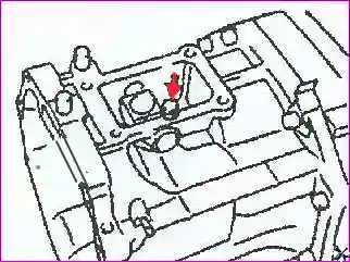
11. Application of sealant to the shift lever cover
Clean the mounting surface of the shift lever cover. Apply a bead of sealant of 1.2 mm diameter to the mounting surface of the shift lever cover.
Note: install the shift lever cover no later than ten minutes after applying the sealant.

12. Installation of the shift lever cover
Install the shift lever cover and secure it with four bolts. Tighten the bolts to the recommended torque.
Tightening torque: 14.4–21.6 N·m.

13. Installation of the reverse light switch
Screw in and tighten to the recommended torque the reverse light switch.
Tightening torque: 35.2–52.8 N·m.
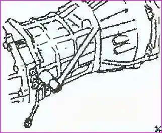
14. Installation of the clutch housing
Install the clutch housing onto the transmission case and secure it with a bolt. Tighten the bolt to the recommended torque.
Tightening torque: 15.5–20.6 N·m.

15. Installation of the release fork support
Screw in and tighten to the recommended torque the clutch release fork support.
Tightening torque: 38–56 N·m.

16. Application of grease to the splines and support head
Apply molybdenum-based grease to the input shaft splines and the release fork support head.

17. Installation of the release fork, bearing and protective cover
Install the release fork, the release bearing and the release fork protective cover.

18. Installation of the clutch slave cylinder
Install the clutch slave cylinder and secure it with bolts. Tighten the bolts to the recommended torque.
Tightening torque: 8.19–15.21 N·m.
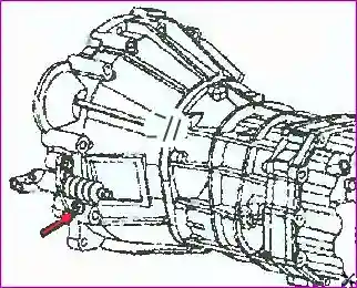
19. Installation of the plugs and sealing washers
Install new sealing washers. Screw in and tighten the hex plugs of the gearbox.
Technical specifications
| Parameters | Value | |
|---|---|---|
| Gear ratios | First gear | 3.8305 |
| Second gear | 2.3300 | |
| Third gear | 1.4364 | |
| Fourth gear | 1.0000 | |
| Fifth gear | 0.7887 | |
| Reverse gear | 4.22 | |


