The car LADA Priora, depending on the configuration, can be equipped with two types of systems:
- Single-channel airbag (basic equipment) - frontal airbag system for the driver.
Regular inertial seat belts for driver and front passenger;
- Four-channel airbag - frontal airbag system for the driver and front passenger with front seat belts with a pretensioner.
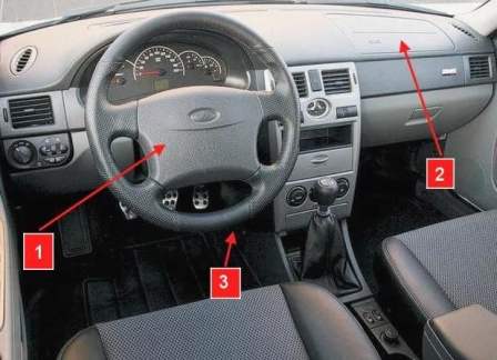
The single-channel airbag system includes:
- - gas generator module (MNPBV) - 1118-8232010-00;
- - airbag system control unit - 2170-3824010-01;
- - connector with rotating device - 2110-3709315-00/1118-3709315-01;
- - steering wheel with signal switch - 1119-3402012-00.
The four-channel airbag system includes:
- - gas generator module (MNPBV) - 2172-8232010-00;
- - airbag system control unit - 2170-3824010-11;
- - connector with rotating device - 2110-3709315-00;
- - steering wheel with signal switch - 1119-3402012-00;
- - passenger airbag module - 2170-8233020-00;
- - front right/left seat belt 2170-8217020/21-10.
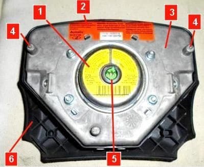
The gas generator module (MNPBV), Figure 2, consists of a gas generator 1, a body 3, with an inflatable cushion folded in it, a facing cover 6 and fasteners.
The gas generator produces gas inside the module to inflate the airbag.
The pyrotechnic substance in the gas generator is ignited by an igniter mounted in the gas generator body.
There are two main types of gas generators.
The pyrotechnic gas generator consists of a body filled with a solid pyrotechnic substance and an igniter.
In it, gas is produced by burning a pyrotechnic substance.
Used in the driver's airbag module.
The hybrid gas generator consists of a body filled with compressed inert gas and pyrotechnic substance, and an igniter.
Used in passenger airbag module.
Igniter-igniter - a device with electrical resistance and pyrotechnic substance.
After receiving an electrical signal from the BUSNPB, the electrical resistance heats up and ignites the pyrotechnic substance of the igniter, followed by ignition of the main mass of the pyrotechnic substance of the gas generator.
Inflatable airbag - a bag of synthetic material mounted in the module housing, which is filled with gas under pressure when the module is triggered.
The airbag is specially folded and covered with a facing cover.
Facing cover - a part that closes the airbag and bursts when the airbag is filled with gas along the structural seam located on the back of the cover.
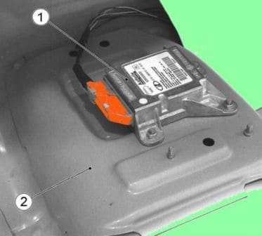
Block 1, figure 3, of the airbag control is fixed with three nuts on the bracket 2 on the floor tunnel and is located under the console of the instrument panel, under the floor mat.
The BUSNPB includes an acceleration sensor and an electronic circuit for generating control signals supplied to the airbag modules and seat belts with a pretensioner.
The control unit converts and processes information coming from the acceleration sensor located in the unit itself, and generates an electricalcue signal to the igniter of the gas generator of the module (s) of the airbag and the pretensioners of the seat belts.
The control unit performs diagnostics of the airbag system, displaying the system status on the diagnostic indicator, and has software for storing fault codes and supporting the diagnostic data exchange channel via the "K" line according to ISO 9141.
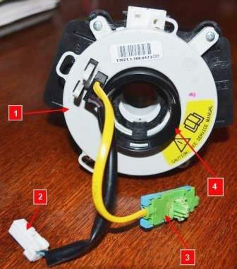
The connector with a rotating device, Figure 4, in the part of the airbag is designed to electrically connect the driver's airbag module located on the steering wheel with the vehicle's electrical wiring.
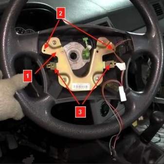
The steering wheel, Figure 5, structurally contains a bracket 1 for mounting the driver's airbag module.
The driver and front passenger seat belts with pretensioner consist of a housing, a reel, a belt pretensioner and a belt with a buckle.
The front seat belt pretensioner is integrated into the reel and ensures that the belt is guided in the direction it is wound onto the reel.
Seat belts with a pretensioner differ from conventional inertia belts by having a gas generator with a tube filled with steel balls and a belt reel with a gear.
Pyrotechnic gas generator.
During combustion, the escaping gas pushes steel balls through the tube onto the gear of the tape spool, ensuring its rotation.
The design of the gas generator is similar to that of the airbag module.
In the design of the seat belt with a pretensioner, there is a mechanism for limiting the degree of tension when the airbag is activated.
The tension limiting mechanism is a mechanical action, it does not require adjustment and maintenance.
When the airbag is triggered after pre-tensioning the belt, under the action of inertia forces acting on the driver and front passenger, the belt belt tension is further increased and the tension degree limiting mechanism automatically maintains the specified value.
Removing and installing units and parts of the SNPB
Before starting work, place the car on the workplace, brake with a parking brake. Switch off the ignition.
Disconnect the ground wire terminal from the battery.
Attention. The BUSNPB scheme has an emergency supply of electricity.
In order to discharge the capacitors, after turning off the ignition, wait at least 10 seconds before working.
Withdrawal of MNPBV
Set the front wheels to straight ahead.
The upper spokes of the steering wheel must be in a horizontal position.
Open left front door.
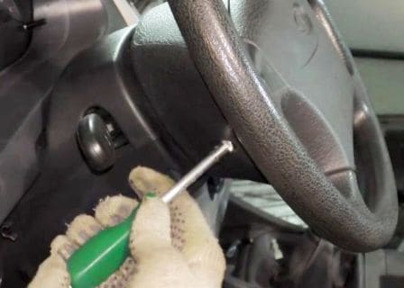
From the outside of the car, to the side of the steering wheel, turn the steering wheel 180 degrees and unscrew the right bolt, Figure 7, securing the gas generator module to the steering wheel.
Return the steering wheel to its original position and unscrew the left bolt ia gas generator module.
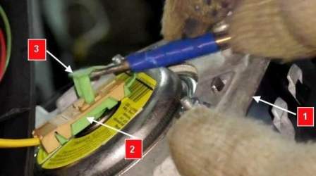
Disconnect module 1, figure 8, from the steering wheel without putting tension on pad harness 2.
Using a flat screwdriver, remove latch 3 from block 2, then, without applying additional lateral forces, disconnect block 2 from module 1 and remove the gas generator module.
Place the failed gas generator module on a flat surface with the facing cover up.
When the L-shaped block 2 is melted, in case of dismantling the triggered gas generator module, disconnect the module by cutting the block harness 2.
Installing MNPBV
Before installing the gas generator module, visually make sure that there are no mechanical damages and that there is a label with a bar code and an identifying number on the gas generator module.
When installing a new gas generator module, tear off part of label 2, Figure 2, with a barcode from the gas generator module and paste it into the "Special Marks" section of the service book, indicating the date of installation and vehicle mileage, the reason for replacement.
While outside the car, to the side of the steering wheel, bring the gas generator module to the installation site in the steering wheel, insert the L-shaped block 2, Figure 8, into the connector of the gas generator module 1 without applying lateral forces until a characteristic locking click is obtained.
Insert retainer 3 into block 2 until it clicks.
Before installing the retainer in the L-shaped block, the airbag module is in the transport position, the contacts of the igniter connector are shunted.
Install the gas generator module in the steering wheel, aligning the clamps 4, Figure 2, on the housing 3 of the gas generator module with mating holes 2, Figure 5, on the bracket 1 of the steering wheel.
Turn the steering wheel 180 degrees and screw in the right bolt, Figure 7, fastening the gas generator module, return the steering wheel to its original position and tighten the left bolt of the gas generator module.
Tighten the bolts securing the gas generator module. Bolt tightening torque 6.4 to 9.6 Nm (0.7 to 0.9 kgf.m).
Removing connector with rotating device
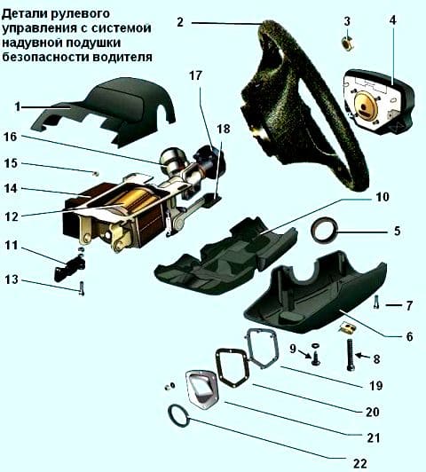
Remove MNPBV. Unscrew two screws 7, figure 6, and two screws 8 and remove the casing 1 facing the top.
Unscrew the three screws 9 and remove the casing 6 facing the lower assembly with the insert 10 of the lower casing.
Remove the O-ring 5 from the ignition switch.
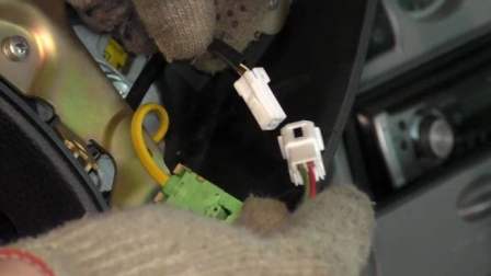
Disconnect block 1, figure 9, of the harness of the device rotating from the block of the horn switch harness.
Set the front wheels to straight ahead.
The upper spokes of the steering wheel must be in a horizontal position.
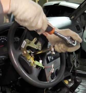
Unscrew the steering wheel nut and remove the steering wheel from the steering shaft, while passing the pads through the hole in the steering wheel hub.
After removing the steering wheel, exclude axial movement of the cylindrical lock 4, Figure 4.
To prevent breakage, do not rotate the cover 1 of the rotating device, as it is automatically fixed.
Remove the wiper and light signaling switches from the connector.
Disconnect the instrument panel harness connectors from the connector.
Loosen the mounting bolt and remove the connector with the rotating device from the steering shaft.
Installing a connector with a rotating device
Before installation, the steering rack must be in the middle position, while the front wheels must be in the straight ahead position of the vehicle.
Install a connector with a rotating device on the steering shaft, do not tighten the connector fastening bolt.
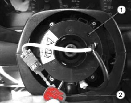
When installing a new connector with a rotating device, remove from the rotating device 1, Figure 11, the red transport key 2, which fixes the movable element of the device in the middle position, turning it around its axis by 90°+30°.
Pass blocks 1 and 4, Figure 9, of the rotating device into the right hole of the steering wheel hub and install the steering wheel on the steering shaft.
In this case, the upper spokes of the steering wheel must be in a horizontal position.
Turn on and tighten the nut 3 of the steering wheel. Nut tightening torque from 31.4 to 51.0 Nm (from 3.2 to 5.1 kgf.m).
Move along the axis of the steering shaft the connector with the device rotating close to the steering wheel hub and then move it in the opposite direction by 2-3 mm.
Tighten the connector fastening bolt.
Connect block 1, figure 9, of the harness of the rotating device to block 2 of the horn switch harness.
Connect the instrument panel harness connectors to the connector.
Install the wiper and light signal switches in the connector.
Install sealing ring 5 on the ignition switch, figure 6.
Install casing 6 lower facing assembly with insert 10 of the lower casing and fix it with screws 9.
Install casing 1 facing upper and fasten it with casing 6 facing lower screws 6 and 8.
Turning the steering wheel to the right and to the left until it stops, make sure that there are no jams, knocks and smooth rotation, as well as that the turn signal lever reset works.
While shaking the steering wheel, make sure that there are no radial and axial play of the steering wheel. Install MNPBV.
Removing the airbag control unit
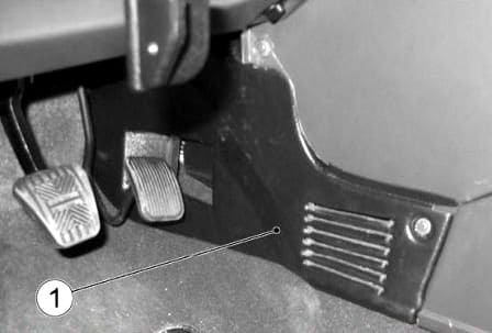
Unscrew the fastening screws and remove the screen 1, figure 12, side left and side screen right.
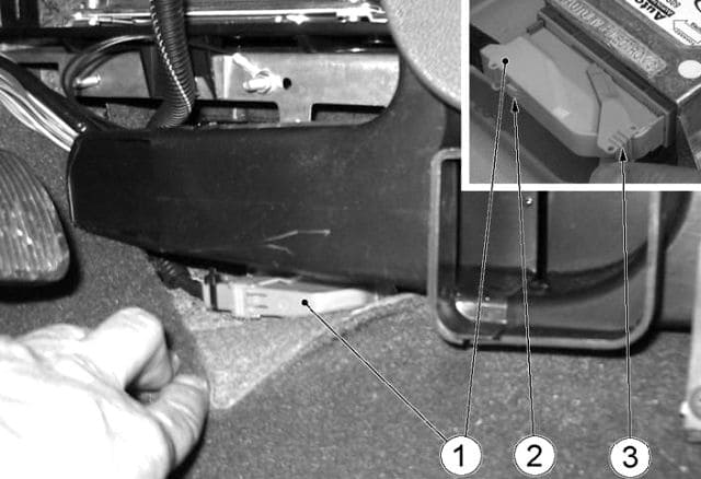
Bend the floor mat, freeing access to block 1, figure 13.
Press latch 2 and, without disconnecting the pads from the BUSNPB connector, move lever 3 as shown in Figure 13, thereby ensuring automatic disconnection of pad 1 from the connector of the SNPB control unit.
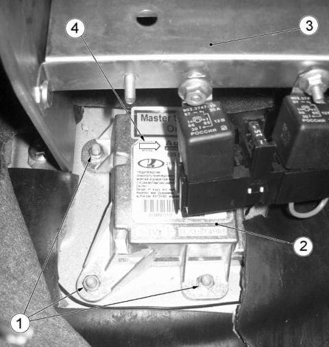
Bend the floor mat from the side of the side right screen, unscrew nuts 1, Figure 14, fastening the control unit 2 of the SNPB control and remove the BUSNPB.
Installing the airbag control unit
Install the control unit in the reverse order of removal.
When installing the BUSNPB, the arrow 4, Figure 14, on the block cover must be directed in the direction of the vehicle.
The tightening torque of the BUSNPB fastening nuts is from 6.4 to 9.6 N.m (from 0.64 to 0.96 kgf.m).
The control unit of the airbag is delivered to the spare parts in a locked state.
After replacing the control unit, it must be unlocked.
Remove MNPBP
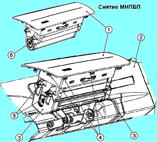
Remove the glove box cover. Unscrew nuts 5, Figure 15, fastening module 1 to bracket 3.
Through the opening of the glove box, alternately acting on the latches 4 of the facing cover of the MNPBP, feeding from below, remove the MNPBP from the instrument panel.
Without tension on the wire harness
Put the failed airbag module on a flat surface with the facing cover up.
In case of dismantling a triggered airbag module, check the wiring harness to the airbag module.
If damage is found to the block to the airbag module, breakage or short circuit of the wires to the airbag module, replace the harness.
Installing MNPBP
Before installing the MNPBP, visually make sure that there are no mechanical damages and that there is a label with a barcode and an identifying number on the module.
When installing a new airbag module, tear off part of the label with a barcode from the module and paste it into the "Special Marks" section of the service book, indicating the date of installation and vehicle mileage, the reason for replacement.
While in the car, bring the airbag module to the installation location in the instrument panel, without applying lateral forces, insert the L-shaped block of the instrument panel wiring harness into connector 6 of the airbag module until a characteristic locking click is obtained.
Insert the latch into the L-shaped block until it clicks.
Before installing the retainer in the L-shaped block, the airbag module is in the transport position, the contacts of the igniter connector are shunted.
Install the airbag module in the instrument panel and fix the cover of the airbag in the instrument panel. Wrap and tighten nuts 5 for fastening the MNPBP to the bracket 3. The tightening torque for the nuts for fastening the MNPBP is from 8 to 16 Nm (from 0.8 to 1.6 kgf.m).
Removing seat belts with pretensioners
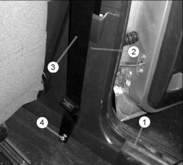
Unscrew the two screws securing the trim 1, figure 15, of the rear door sill, remove the trim.
Remove the facings and caps from the heads of the seat belt mounting bolts.
Remove the bolt 4, figure 16, fastening the belt branch 3 on the floor threshold.
Remove B-pillar lower trim 2.
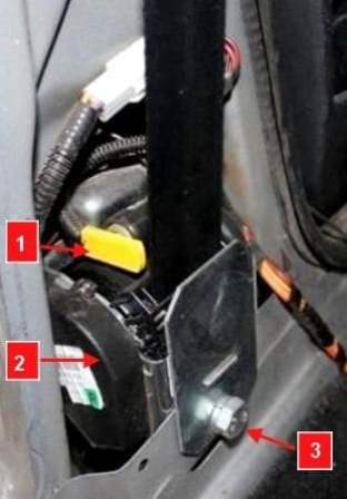
Disconnect connector 1, figure 17, from the inertial coil gas generator 2.
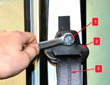
Remove the bolt 1, figure 18, fastening the seat belt bracket 2 on the B-pillar.
Remove bolt 3, figure 17, fastening coil 2 and remove the front seat belt with coil assembly.
Remove the bolt securing the front seat belt buckle to the seat bracket and remove the buckle.
Installing seat belts with pretensioners
Install the seat belts in the reverse order of removal.
After opening the locks, the seat belts must return from their working position to their original position freely without jamming.
Before installing the seat belts, remove the transport washers. The tightening torque of the seat belt mounting bolts is from 18 to 32 Nm.
After completing the removal / installation of the components of the airbag, connect the terminal of the "ground" wire to the battery.
The ignition must be turned off when connecting the ground wire terminal to the battery. In this case, no one should be in the car.
Check the operation of the SNPB
For safety reasons, the first ignition switch on a vehicle with a replaced driver airbag module should be as follows:
- - open the driver's door;
- - without sitting on the seat, with your right hand, placing it under the steering wheel, turn on the ignition, while The person performing this operation must not be between the steering wheel and the driver's seat.
After turning on the ignition, if there are no malfunctions, the diagnostic indicator (orange symbol) should turn on for 3-4 seconds and turn off.
Turn off the ignition.
In case of removal/installation of the steering wheel, by pressing the switches located in the horizontal spokes of the steering wheel, make sure that there is a sound signal.
Diagnosis of SNAP
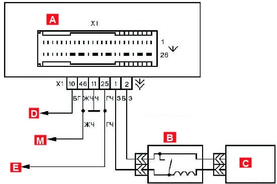
Scheme of electrical connections of the single-channel airbag system of LADA Priora is shown in Figure 19.
The purpose of the conclusions of the SNPB control unit is shown in Table 1.
- 1 - Driver's airbag, contact "-"
- 2 - Driver's airbag, contact "+"
- 3 - passenger airbag, contact "-"
- 4 - passenger airbag, contact "+"
- 7 - Passenger pretensioner, contact "-"
- 8 - Pretensioner RB driver, contact "+"
- 9 - Pretensioner RB driver, contact "-"
- 10 - Diagnostic indicator in instrument cluster
- 11 - Common wire (ground)
- 25 - To terminal "15" of the ignition switch
- 30 - Passenger pretensioner, contact "+"
- 46 - Contact "M" of the diagnostic block (K-line)
To view fault codes and parameters of the SNPB, the DST-2M (DST-10S) diagnostic device is used, which is connected to the vehicle's diagnostic block.
The list of fault codes displayed by the diagnostic tool in the "Faults" mode is given in Table 2
Code - Description of code
B1001
Leak on positive contact 30 "+" RB passenger
Leak on minus contact 7 "-" RB passenger
High resistance of contacts 7 and 30 RB passenger
Low resistance of contacts 7 and 30 RB passenger
B1002
Leakage on plus pin 8 "+" RB driver
Leak on minus contact 9 "-" RB driver
High resistance of pins 8 and 9 of the driver RB
Low resistance of contacts 8 and 9 of the driver RB
B1003
Leakage on positive pin 2 "+" PB driver
Leakage on minus contact 1 "-" PB driver
High resistance pins 1 and 2 PB driver
Low resistance pins 1 and 2 PB driver
B1004
Leakage on plus pin 4 "+" PB passenger
Leak on minus contact 3 "-" PB passenger
High resistance of pins 3 and 4 PB passenger
Low resistance of passenger PB pins 3 and 4
B1040
Leakage on the positive terminal 10 of the diagnostic signaling device
Leakage on the minus contact 10 of the diagnostic signaling device
B1042
Power supply voltage out of operating range (≥ 16.5 V or ≤ 10.0 V)
Low supply voltage due to battery bounce
B1044
- Incorrect connection of fuse lines
B10C0 - B10CE,
B1081 - B1084,
B10B1 - B10BE,
B109A - B109C
- - Internal malfunction of the airbag control unit
If a "High contact resistance" fault is found, check:
- - reliability of connecting the block of the instrument panel harness to the BUSNPB;
- - the reliability of the connection of the block to the corresponding component of the SNPBV (MNPBV and the rotating device, MNPBP, seat belt pretensioner);
- - the corresponding electrical circuit to the BUSNPB for an open (before checking the circuit, be sure to disconnect the pads from the BUSNPB and the corresponding component of the SNPB).
If a "Low Contact Resistance" fault is found, check:
- - the completeness and reliability of fixing the block in the connector of the corresponding component of the SNPBV (the cause of this malfunction may be an uninstalled latch in the L-shaped block to the MNPBV, MNPBP, an unfixed block in the connector of the seat belt pretensioner, rotating device);
- - the corresponding electrical circuit to the BUSNPB for a short circuit between the contacts (before checking the circuit, be sure to disconnect the pads from the BUSNPB and the corresponding SNPB component).
If a malfunction is detected "Internal malfunction of the SNAP control unit", replace the BUSNPB.
The list of parameters displayed by the diagnostic tool in the "Parameters. Current state of the airbag" mode is given in Table 3.
|
Parameter |
Name |
Unit |
Single-channel SNPB |
Four-channel SNPB |
|---|---|---|---|---|
|
Ref PB water |
Chain resistance airbags driver |
Ohm |
2.70-3.30 |
2.70-3.30 |
|
Ref PB pass |
Resistance airbag circuits passenger |
Ohm |
12.40-13.20 |
1.70-2.30 |
|
Spir RB water |
Chain resistance pretensioner seat belt driver |
Ohm |
12.40-13.20 |
1.70-2.30 |
|
Ref RB pass |
Chain resistance belt pretensioner passenger safety |
Ohm |
12.40-13.20 |
1.70-2.30 |
If the control unit is in a locked state, as evidenced by the constant burning of the signaling device after the ignition is turned on, it must be unlocked using the DST-2M device, for which, in the SNPB menu, select: "Record mode" "ECU lock" "CU lock - OFF"
If it is necessary to force the deactivation of the passenger airbag module in the quad airbag system, in the airbag menu, select: "Record mode" "Passenger airbag off" "Passenger airbag OFF" If the forced deactivation (blocking) function of the airbag module in the quad airbag system is activated , then after turning on the ignition, the diagnostic indicator will turn on for 3-4 seconds, then blink 12 times, informing about the blocking of the MNPBP, and turn off.


