
The vehicle uses DC electrical equipment with a nominal voltage of 12 V.
The vehicle's electrical equipment uses a single-wire design: the negative terminals of the power sources and consumers are connected to the ground, which functions as a second wire. The vehicle body, in turn, serves as the "ground."
Power is supplied to the consumers from the battery (when the engine is not running) and the generator (when the engine is running).
A distinctive feature of the electrical system is the connection of several components (windshield washers, interior lights, door locks, etc.) through an electronic control unit for the interior electrical system and the anti-theft alarm.
The electronic unit allows you to delay the switching on and off of electrical devices and change the pause time depending on the selected control algorithm.
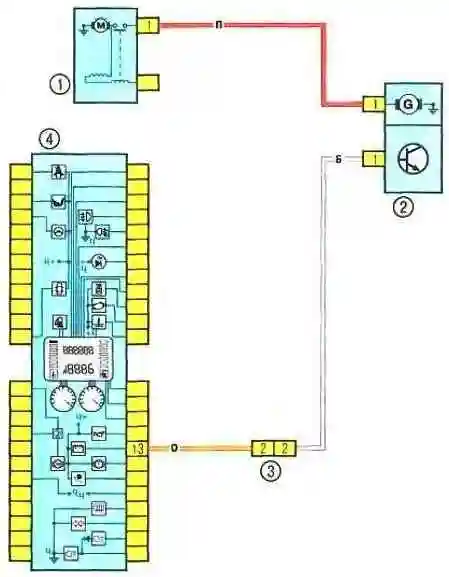
Diagram 1. Battery charging circuit
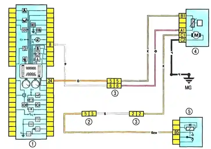
Diagram 2. Fuel pump and fuel level sensor
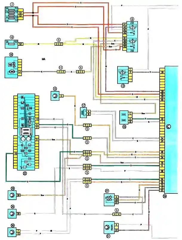
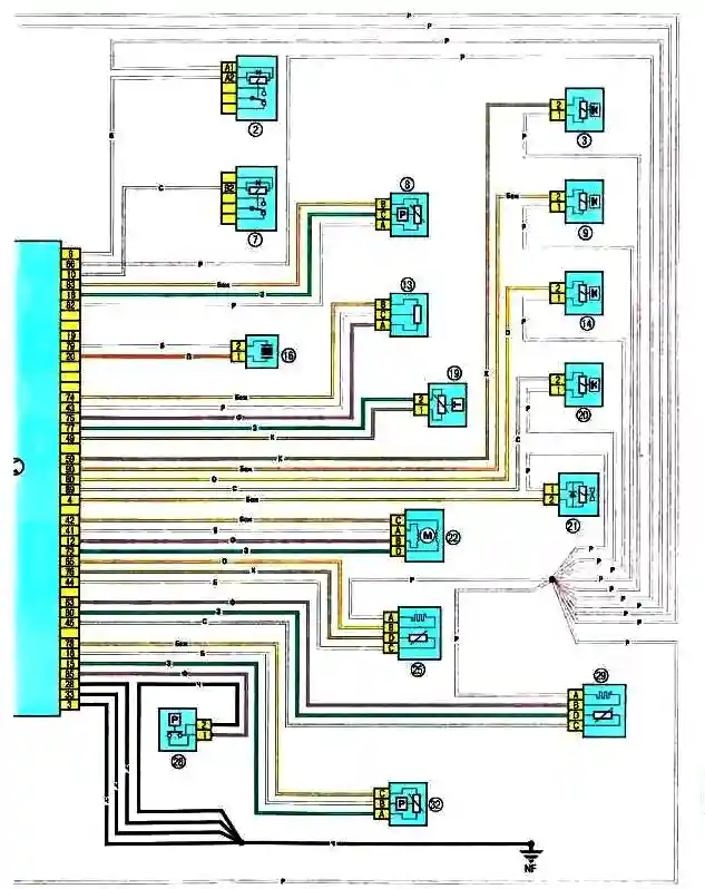
Diagrams 3, 4 Engine management system: 1 - fuse box 5978 in the engine compartment (see Fig. 10.2a and 10.2b); 2 - relay box 784 in the engine compartment, relay 700; 3 - injector of the first cylinder; 4 - fuse box in the passenger compartment (see Fig. 10.1); 5 - engine compartment/passenger compartment wiring connector (monobloc); 6 - relay box 1047 in the engine compartment, relays 236 and 238; 7 - Relay box 784 in the engine compartment, relay 474; 8 - Coolant pressure sensor (vehicles with air conditioning); 9 - Injector for cylinder 2; 10 - Fuel pump and fuel level sensor; 11 - Instrument cluster/left rear body wiring connector; 12 - Relay box in the engine compartment, relay 234; 13 - Throttle position sensor; 14 - Injector for cylinder 3; 15 - Air conditioning control panel; 16 - Knock sensor; 17 - Crankshaft position sensor; 18 - Ignition module; 19 - Air temperature sensor; 20 - Injector for cylinder 4; 21 - Evaporative absorber; 22 - Idle air control stepper motor; 23 - Instrument cluster; 24 - ECU; 25 - Oxygen concentration diagnostic sensor; 26 - Passenger compartment junction box; 27 - Coolant temperature sensor; 28 - Power steering pressure switch; 29 - Oxygen sensor of the engine management system; 30 - Diagnostic connector; 31 - Speed sensor; 32 - Absolute pressure sensor in the intake manifold.
Diagram 3, 4. Engine management system diagrams
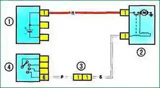
Diagram 5. Engine starting system: 1 - Battery; 2 - Starter; 3 - Engine compartment/passenger compartment wiring connector (monobloc); 4 – Ignition switch
Diagram 5. Engine starting system
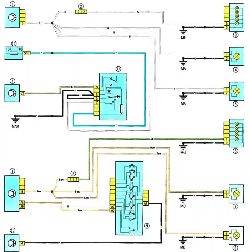
Diagram 6. Turn signals and hazard warning lights: 1 - passenger compartment junction box; 2 - instrument panel/left rear body wiring connector; 3 - right rear light; 4 - right front direction indicator; 5 - right direction indicator repeater; 6 - left rear light; 7 - left front direction indicator; 8 - left direction indicator repeater; 9 - exterior lighting and direction indicator switch lever with horn button; 10 - diagnostic connector; 11 - hazard warning lights switch; 12 - Passenger compartment fuse box
Diagram 6. Direction indicator and hazard warning lights
On-board electrical equipment fault diagnostics
A typical electrical circuit may include a main electrical component, various switches, relays, electric motors, fuses, fusible links, or circuit breakers associated with that component, wiring, and connectors used to connect the main component to the battery and body ground.
Before troubleshooting any electrical circuit, carefully study the relevant diagram to understand its functionality as clearly as possible.
The troubleshooting area is usually narrowed by gradually identifying and eliminating normally functioning components of the same circuit.
If several components fail simultaneously, or The most likely cause of failure in circuits is a blown fuse or a broken ground connection (different circuits can often be shorted to the same fuse or ground terminal).
Electrical equipment failures are often explained by simple causes, such as corrosion of connector contacts, a blown fuse, a blown fuse link, or a damaged relay.
Visually inspect the condition of all fuses, wiring, and circuit connectors before proceeding with a more detailed check of the circuit's components.
If using diagnostic tools to troubleshoot a fault, carefully plan (in accordance with the attached electrical diagrams) which points in the circuit and in what sequence the tool should be connected to ensure the most effective fault detection.
Basic diagnostic tools include an electrical circuit tester or voltmeter (a 12-volt test lamp with a set of connecting wires can also be used), an open circuit indicator (test probe) that turns on a lamp, Your own power source and a set of connecting cables.
Also, you should always have a set of jumper cables in your car for jump starting from an external source (another car's battery), equipped with alligator clips and, preferably, a circuit breaker.
These can be used to bypass and connect various electrical components when diagnosing a circuit. As already mentioned, before testing the circuit using diagnostic equipment, determine its connection locations using the diagrams.
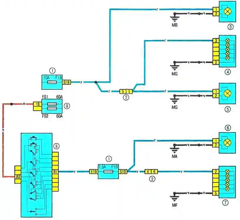
Diagram 7. Parking Light: 1 - Passenger compartment fuse box: 2 - Instrument cluster/left rear body wiring connector; 3 - Left front headlight parking light; 4 - Left rear light; 5 - License plate light; 6 — right front side light; 7 — right rear light; 8 — exterior lighting and turn signal switch lever with horn button; 9 — 597A fuse box in the engine compartment.
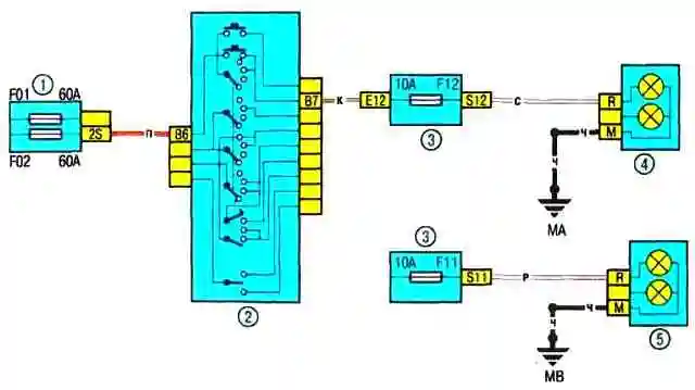
Diagram 8. High beam
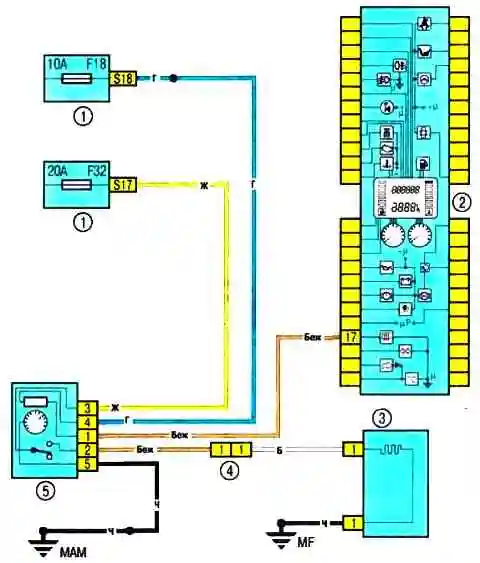
Diagram 9. Rear window heating: 1 – fuse box in the passenger compartment; 2 – instrument cluster; 3 – rear window heating; 4 – instrument panel/left rear body wiring connector; 5 — Rear window heating switch
Diagram 9. Rear window heating
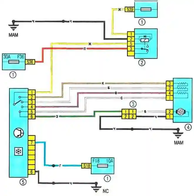
Diagram 10. Heating and ventilation system electric fan: 1 — passenger compartment fuse box; 2 — relay 233; 3 — cooling system/instrument panel electric fan wiring connector; 4 – electric fan of the heating and ventilation system; 5 — Control unit for the heating and ventilation system of the passenger compartment
Diagram 10. Electric fan of the heating and ventilation system of the passenger compartment
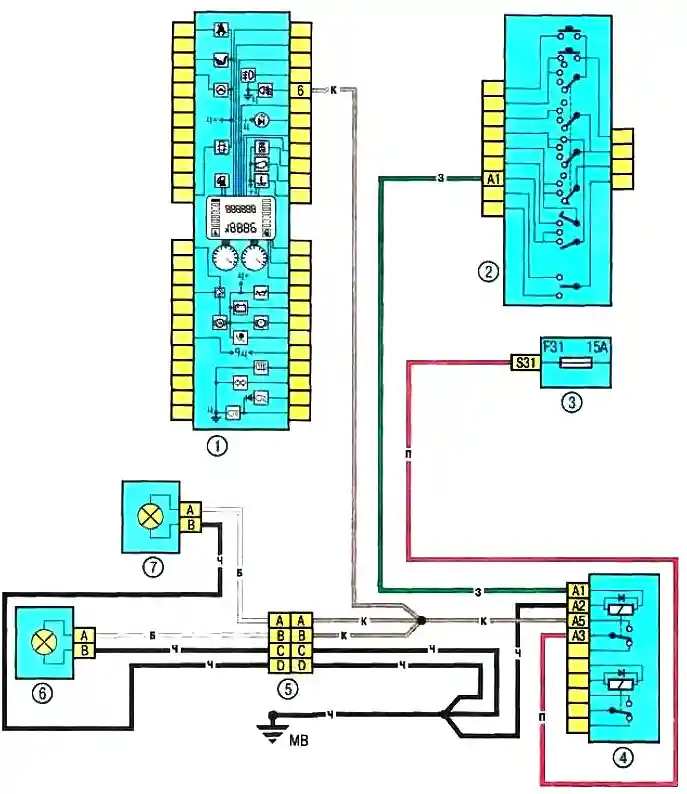
Diagram 11. Front fog lights: 1 — instrument cluster: 2 — lever of the switch of external lighting and turn signals with the signal button; 3 – fuse box in the passenger compartment; 4 – relay box 299 in the engine compartment; 5 – instrument panel/fog light wiring connector; 6 – left fog light; 7 – Right fog light
Diagram 11. Front fog lights
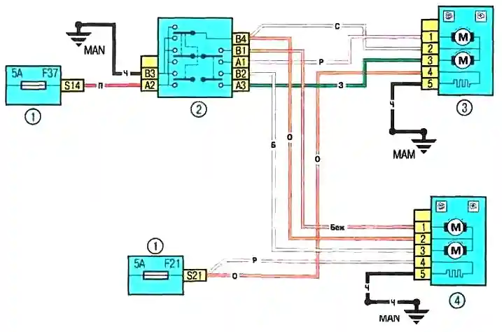
Diagram 12. Electric mirrors: 1 – fuse box in the passenger compartment; 2 – outside rearview mirror control unit; 3 – electric drive of the left outside rearview mirror with electric heating; 4 - Electric drive of the right outside rearview mirror with heating
Diagram 12. Electric drive of mirrors
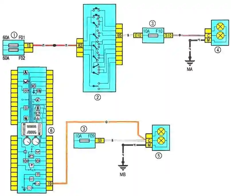
Diagram 13. Low beam: 1 - 597A fuse box in the engine compartment; 2 - lever of the outside lighting and turn signal switches; 3 – Passenger compartment fuse box; 4 – Right front headlight; 5 – Left front headlight; 6 – Instrument cluster.
Diagram 13. Low beam
Voltage checks are performed if there is a fault in the electrical circuit.
Connect one lead of the electrical circuit tester to the negative terminal of the battery or ensure good contact with the vehicle body.
Connect the other lead of the tester to the connector terminal of the circuit being tested, preferably the one closest to the battery or fuse.
If the tester's indicator lamp lights, there is voltage on that section of the circuit, confirming the integrity of the circuit between that point and the battery.
Proceed in the same manner to test the rest of the circuit. Detecting a power supply voltage fault indicates a fault between this point in the circuit and the last previously tested point (where power was present).
In most cases, the cause of the fault is loose connectors and damage to the contacts themselves (oxidation).
Finding the Short Circuit
One method for locating a short circuit is to remove the fuse and replace it with a test lamp or voltmeter. There should be no voltage in the circuit.
Tug the wiring while observing the test lamp. If the light starts to flash, there is a short to ground somewhere in the wiring harness, possibly caused by chafing of the wire insulation.
A similar check can be performed for each component in the electrical circuit by turning on the corresponding switches.
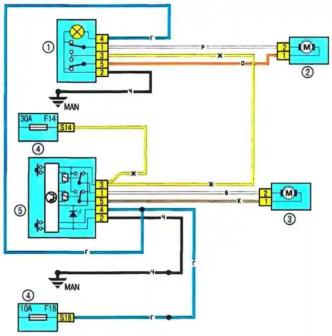
Diagram 14. Front Door Power Windows: 1 – Front passenger door power window switch; 2 – window lifter motor ka front passenger door; 3 - electric motor of the driver's door window; 4 - fuse box in the passenger compartment; 5 — Driver's door power window pulse switch
Diagram 14. Front door power window
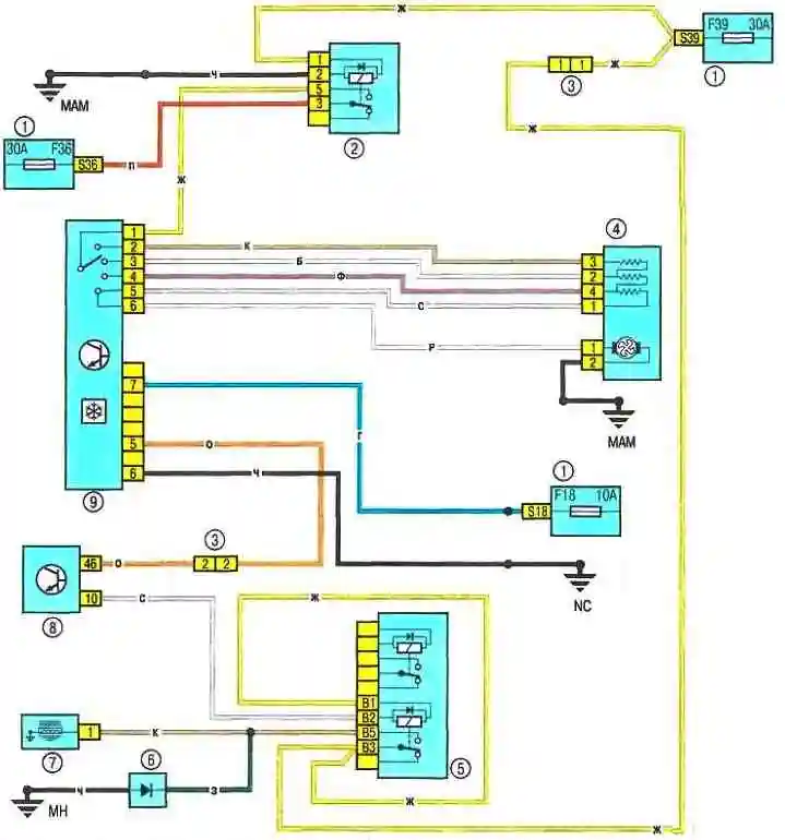
Diagram 15. Heating (air conditioning) and ventilation system electric fan: 1 — passenger compartment fuse box; 2 — relay 233; 3 – Engine compartment/passenger compartment wiring connector (monobloc); 4 – Heating and ventilation system electric fan; 5 – Relay box 784 in the engine compartment; 6 – Air conditioner and power steering diode; 7 – Air conditioner compressor electromagnetic clutch; 8 – ECU; 9 — Control unit for the heating and ventilation system of the passenger compartment
Diagram 15. Electric fan of the heating (air conditioning) and ventilation system of the passenger compartment
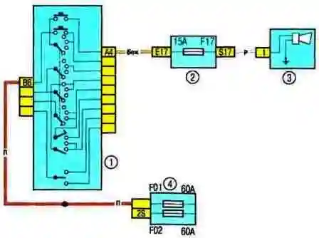
Diagram 16. Horn
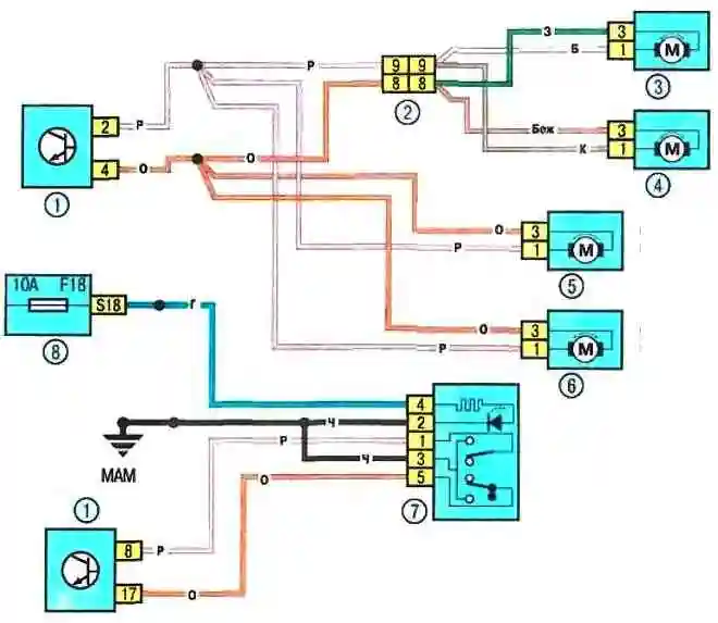
Diagram 17. Central locking system: 1 - Passenger compartment junction box; 2 - Instrument panel/left rear body wiring connector; 3 - Right rear door lock electric drive; 4 – electric drive of the left rear door lock; 5 – electric drive of the right front door lock; 6 – electric drive of the driver’s door lock; 7 – central locking system switch; 8 — Passenger compartment fuse box
Diagram 17. Central locking system
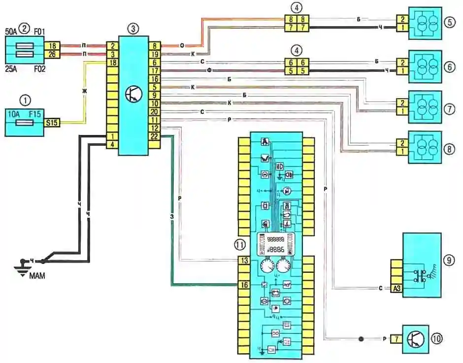
Diagram 18. ABS control system: 1 — passenger compartment fuse box; 2 — fuse box 597C in the engine compartment; 3 — ABS control unit; 4 - Instrument cluster/left rear wiring connector; 5 - Right rear wheel speed sensor; 6 - Left rear wheel speed sensor; 7 - Left front wheel speed sensor; 8 - Right front wheel speed sensor; 9 - Brake light switch; 10 - Diagnostic connector; 11 – Instrument Cluster
Diagram 18. ABS Control System
Checking the Ground Connection
Disconnect the battery and connect one of the test light leads with a battery-powered test lamp to a known good ground connection.
Connect the other test light lead to the wiring harness or connector terminal being tested.
If the light illuminates, the ground connection is good (and vice versa).
The continuity test is performed to detect open circuits.
After disconnecting the circuit power, test it using a battery-powered test light.
Connect the test light leads to both ends of the circuit. If the test lamp lights, there is no open circuit.
If the lamp does not light, this indicates an open circuit.
You can similarly check the switch by connecting a test lead to its contacts.
When the switch is turned to the "ON" position, the test lamp should light.
Locating the Open Circuit
When diagnosing a suspected open circuit in an electrical circuit, visually identifying the cause of the malfunction can be quite difficult, as it can be difficult to visually inspect the terminals for corrosion or damage to their contacts due to limited access (the terminals are usually covered by the connector housing).
A sharp jerk of the wiring harness connector housing on the sensor or the wiring harness itself often restores contact.
Not for Keep this in mind when attempting to isolate the cause of a circuit failure suspected of being open.
Intermittent failures may be due to terminal oxidation or poor contact quality.
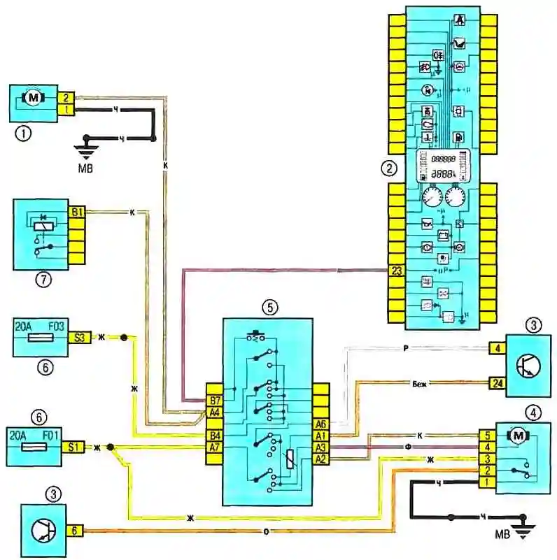
Diagram 19. Windshield wiper and washer, headlight washer: 1 – pump windshield washer; 2 - instrument cluster; 3 - passenger compartment switch unit; 4 - windshield wiper motor; 5 - windshield wiper and washer switch lever with trip computer display mode button; 6 - passenger compartment fuse box; 7 – Relay box 299 in the engine compartment, relay 753
Diagram 19. Windshield wiper and washer, headlight washer
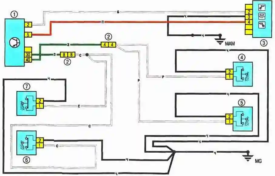
Diagram 20. Car interior light: 1 – interior switch unit; 2 – Instrument cluster/left rear body wiring connector; 3 – Interior light; 4 – Driver’s door limit switch; 5 – Right front door limit switch; 6 – Right rear door limit switch; 7 — Left rear door limit switch
Diagram 20. Interior light.
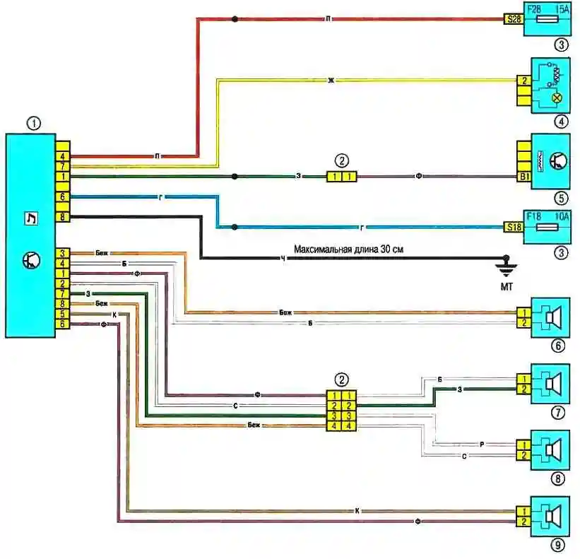
Diagram 21. Connecting the speakers of the acoustic system: 1 — car radio; 2 — engine compartment/interior wiring connector (monobloc); 3 — fuse box in the cabin; 4 – cigarette lighter; 5 – vehicle speed sensor; 6 – right front speaker; 7 – right rear speaker; 8 – left rear speaker; 9 – left front speaker; 10 – Instrument cluster/left rear body wiring connector.
Diagram 21. Connecting the sound system speakers.
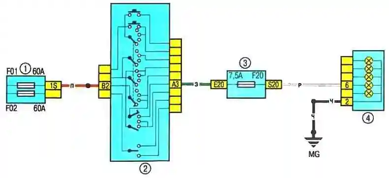
Diagram 22. Rear fog light: 1 – 597A fuse box in the engine compartment; 2 – Exterior lighting and turn signal switch lever with horn button; 3 – Interior fuse box; 4 – Left rear light.
Diagram 22. Rear fog light.

")
")
")
")
")
")
")
")