


128-pin electronic control unit
The S3000 unit from SAGEM manages the injection and ignition systems and features multipoint sequential injection (F4R, K4J engines).
The camshaft does not have a TDC sensor for the first cylinder piston; therefore, synchronisation of the system component control with the engine operating cycle is performed by software using the TDC sensor signals.
Engine starting is carried out in semi-sequential mode (to synchronise system control with the engine cycle), then switches to sequential synchronised mode.
K4M engines are equipped with a TDC sensor for the first cylinder piston on the camshaft.
Synchronisation of system component control with the engine cycle (determination of TDC of the 1st cylinder piston) is achieved using the signal from this sensor.
Engine starting occurs in semi-sequential mode (to synchronise system control with the engine cycle), then switches to sequential synchronised mode.
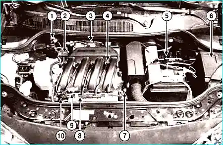
Fig. 1. K4J injection system component locations in the engine bay of the Mégane 2: 1 - fuel vapour recirculation solenoid valve; 2 - absolute pressure sensor; 3 - electronic throttle body; 4 - ignition coil; 5 - injection ECU; 6 - protection and switching unit; 7 - coolant temperature sensor; 8 - knock sensor; 9 - air temperature sensor; 10 - fuel rail and injectors
The injection system malfunction warning lamp on the instrument panel is active
Use of a dedicated injection system malfunction warning lamp (OBD «On-Board Diagnostics» warning lamp).
Its presence is due to the installation of the «On-Board Diagnostics system».
Special precautions due to the electronic engine immobiliser system
Due to the installation of the third-generation electronic engine immobiliser system, ECU replacement must be carried out using a specific procedure.
Fuel supply system without fuel return to the tank
The pressure regulator is integrated in the «fuel pump – fuel level sensor» assembly. Idle speed mode (hot engine).
Nominal idle speed
The idle speed is corrected depending on: – coolant temperature; – battery voltage;
- air conditioning status (on/off);
- oil pressure (vehicle with K4M engine);
- automatic gearbox selector lever position (vehicle with F4R engine).
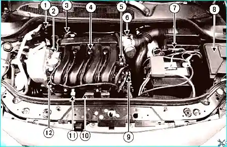
Fig. 2. K4M injection system component locations in the engine bay of the Mégane 2: 1 - fuel vapour recirculation solenoid valve; 2 - camshaft phaser solenoid valve; 3 - absolute pressure sensor; 4 - ignition coil; 5 - camshaft position sensor; 6 - electronic throttle body; 7 - injection ECU; 8 - protection and switching unit; 9 - coolant temperature sensor; 10 - knock sensor; 11 - air temperature sensor; 12 - fuel rail and injectors
Maximum crankshaft speed
Protection against exceeding the maximum permissible crankshaft speed – cold K4J engine.
If the coolant temperature is below 60 °C, or within 10 s after engine start, fuel injection is cut off at 5800 rpm.
K4M
If the coolant temperature is below 75 °C, or within 10 s after engine start, fuel injection is cut off at 5800 rpm.
F4R
If the coolant temperature is below 75 °C, or within 17 s after engine start, fuel injection is cut off at 5900 rpm.
Protection against exceeding the maximum permissible crankshaft speed – hot engine
When the engine is hot, this value returns to its normal value.
K4J and K4M
Fuel injection is cut off at 6500 rpm, regardless of the gear engaged (manual or automatic transmission).
F4R
Fuel injection is cut off at 6000 rpm (manual transmission) and 6300 rpm (automatic transmission), regardless of the gear engaged.
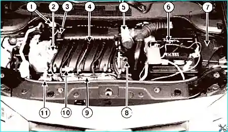
Fig. 3. F4R injection system component locations in the engine bay of the Mégane 2: 1 - fuel vapour recirculation solenoid valve; 2 - camshaft phaser solenoid valve; 3 - absolute pressure sensor; 4 - ignition coil; 5 - electronic throttle body; 6 - injection ECU; 7 - protection and switching unit; 8 - coolant temperature sensor; 9 - knock sensor; 10 - air temperature sensor; 11 - fuel rail and injectors
K4M camshaft phaser
The valve timing varies continuously between 0 and 43° of crankshaft rotation.
The phaser is controlled by a solenoid valve supplied with a variable duty cycle signal from the injection ECU.
F4R
The phaser is a solenoid valve powered by the injection ECU in an on/off manner.
Control of the engine cooling fan and the coolant overheat warning lamp.
The request comes from the injection ECU via the multiplex network (centralised coolant temperature management function).
The fan motor supply voltage is provided by the protection and switching unit.
Air conditioning compressor control
The request comes from the injection ECU via the multiplex network.
The request is generated based on climate control operating data and coolant temperature.
The air conditioning compressor is powered via the protection and switching unit.
Fuel pump control
The request comes from the injection ECU. The fuel pump supply voltage is provided by the protection and switching unit.
Speed regulator/limiter
The speed regulator/limiter and air conditioning system are configured automatically.
Oxygen sensor
Two oxygen sensors are used, mounted upstream and downstream of the catalytic converter.
Throttle body
Air supply and idle speed are regulated by the electronic throttle body.
Protection and switching unit
The unit supplies voltage to the following components:
- ignition coils;
- fuel pump;
- air conditioning compressor;
- cooling fan;
- some injection system actuators (injectors, canister purge solenoid valve, etc.).
The protection and switching unit is located in the engine compartment next to the battery.
The unit provides circuit protection for certain electrical devices.
To perform this function, the unit includes fuses and several built-in relays:
- relay «+» after ignition switch;
- fuel pump relay;
- air conditioning compressor relay;
- engine cooling fan relay;
- starter relay (control of the starter solenoid).
These relays are fixed.
Injection ECU
The unit continuously receives information via the multiplex network about the electrical power generated by the alternator.
This is necessary to ensure that the vehicle's electrical consumption does not exceed the alternator's capacity.
The main objective is to ensure battery charging.
Accelerator pedal
Replacing the accelerator pedal is straightforward.
The ECU takes the value read at ignition switch-on as the reference value for the released pedal.
The sensor, in the form of a dual-track potentiometer, provides the ECU with information on the accelerator pedal position.
The sensor signal voltage has two conductive tracks with different resistances.
The first track provides a voltage (0–5 V) twice as high as the signal voltage of the second track (0–2.5 V).
Comparing the voltages of both signals allows the generated signal to be verified against the actual value.
Idle speed mode
The idle speed is increased by a maximum of 160 rpm if the battery voltage is below 12.7 V.
If a fault of the absolute pressure sensor is present and stored, the target idle speed is set to:
- 896 rpm (K4J and K4M engines);
- 1024 rpm (F4R engine).
The S3000 injection system controls the switching on of three warning lamps and the display of messages according to the severity of detected faults, in order to determine the necessary diagnostic action.
The injection ECU controls the switching on of warning lamps and the display of messages on the instrument panel.
These warning lamps illuminate during the engine start phase, as well as in the event of an injection system fault or engine overheating.
Commands to switch on the warning lamps are sent to the instrument panel via the multiplex network.
Principle of operation of the warning lamps
When starting the engine by pressing the «start» button.
The «On-Board Diagnostics» warning lamp illuminates for approximately 3 s and then goes out.
In the event of an injection system fault (severity level 1)
The message «injection a controller» (check injection) is displayed, accompanied by the illumination of the «service» warning lamp.
This indicates a reduced safety level and the need to use the engine in a reduced-power mode.
The owner should have the fault repaired as soon as possible.
These faults may be caused by:
- fault in the electronic throttle body;
- fault in the accelerator pedal position sensor;
- fault in the absolute pressure sensor;
- fault in the ECU;
- faults in the actuator power supply circuits;
- faults in the ECU power supply circuit.
In the event of a serious injection system fault (severity level 2)
A red engine symbol and the message «stop» (only on the matrix display) are shown, along with the message «injection defaillante» (injection faulty), accompanied by the «stop» warning lamp and an audible signal.
In the event of engine overheating
An engine overheat symbol (only on the matrix display) appears with the message «surchauffe moteur» (engine overheating), accompanied by the «stop» warning lamp and an audible signal.
In this case, the vehicle must be stopped immediately.
When a fault is detected that causes the exhaust emission limits to be exceeded.
The «On-Board Diagnostics» warning lamp with the engine symbol illuminates:
- «flashing» if the fault could damage the catalytic converter (misfires that could destroy it).
In this case, the vehicle must be stopped immediately.
- «steady» if the exhaust emission limits are exceeded (misfires causing increased emissions, catalytic converter fault, oxygen sensor faults, inconsistency between oxygen sensor signals, canister fault).
Communication between the injection ECU and the climate control ECU
The climate control system is managed by several ECUs.
The injection ECU functions include:
- management of cooling capacity based on requests from the passenger compartment and the pressure value in the circuit;
- determination of the power consumed by the air conditioning compressor based on the circuit pressure value;
- authorisation of control of the engine cooling fan according to vehicle speed and circuit pressure;
- authorisation or prohibition of compressor activation.
When the air conditioning is switched on, the climate control panel requests authorisation to activate the compressor.
The injection ECU authorises or prohibits:
- compressor operation;
- engine cooling fan operation;
- engine transition to idle.
Control commands for the engine cooling fan and compressor are sent by the injection ECU via the multiplex network.
These commands are generated based on climate control operating data, coolant temperature, and vehicle speed.
The fan and compressor supply voltage is provided by the protection and switching unit.
Information used by the climate control ECU is transmitted via the multiplex network:
- pin 4 AA – «CAN HIGH» multiplex network line;
- pin 3 AA – «CAN LOW» multiplex network line.
The injection ECU receives information from the refrigerant pressure sensor via the pins:
- J3 – refrigerant pressure sensor signal;
- J2 – 5 V «+» power supply for the pressure sensor;
- K2 – pressure sensor earth.
Air conditioning compressor engagement algorithm
During certain operating periods, the injection ECU prohibits compressor operation.
Algorithm for maintaining dynamic performance during hill starts.
To facilitate hill starts, the compressor is disabled for 20 s.
Algorithm for protection against exceeding the maximum engine speed.
The compressor is stopped in the following cases:
- instantaneous crankshaft speed exceeds 6300 rpm;
- crankshaft speed exceeds 5760 rpm for more than 10 s.
Overheat protection algorithm
The compressor does not operate when the coolant temperature exceeds 115 °C under high engine speed and load.
Engagement conditions:
- engine speed above 4512 rpm and intake manifold pressure below 700 mbar.
Disengagement conditions:
- after a 10 s delay, the centralised coolant temperature management function is activated.
Throttle body operating principle
The throttle body regulates idle speed and the amount of air entering the engine.
It consists of an electric motor and a potentiometric throttle position sensor with two conductive tracks.
At idle, the throttle position is set according to the target idle speed, which depends on the number of activated high-power consumers (air conditioning) and engine operating conditions (air and coolant temperatures).
When the accelerator pedal is pressed, the throttle opens to the corresponding angle.
However, to improve driving comfort, the throttle opening is not directly proportional to the driver's input.
To avoid jerking, facilitate gear changes, and ensure safety, the throttle body allows engine torque to be modulated.
Throttle body limp-home modes
There are four throttle body limp-home modes.
1. Dynamic performance limitation mode
This mode is activated in the event of faults in electrical circuits for which a safe degraded solution exists (fault of one of the two tracks of the accelerator pedal position sensor or the throttle body).
In this mode, acceleration performance and maximum throttle opening are limited (maximum speed 90 km/h for manual transmissions, 100 km/h for automatic transmissions).
2. Loss of driver control mode
This mode is also called «electrical limp-home position».
This mode is activated when there is a complete loss of accelerator pedal position information, but the injection ECU continues to monitor engine cylinder air filling (the throttle actuator remains controllable).
In this mode, the injection ECU sets the target pedal position for each gear and switches the engine to idle when the brake pedal is pressed.
In this case, the maximum crankshaft speed in neutral is limited to 2500 rpm.
3. Mechanical limp-home position mode
This mode is activated in the event of faults causing a loss of throttle control (the throttle actuator is inoperative).
The throttle is then in the mechanical rest position; the injection ECU limits crankshaft speed by cutting injection and limits torque by deactivating cylinders (cutting ignition and injection) depending on the accelerator pedal position.
As a result, the maximum crankshaft speed under full load or in neutral remains limited to 2500 rpm.
4. Pedal position tracking mode
In the event of loss of intake manifold pressure information, the throttle opening is directly proportional to the accelerator pedal position.
NOTE
When switching to any of these modes, the injection system fault warning lamp illuminates on the instrument panel.
Idle speed correction depending on coolant temperature (F4R engine)
Coolant temperature, °C – Engine crankshaft speed, rpm:
- -20 – 1072;
- 20 – 976*;
- 40 – 896;
- 80 – 752;
- 100 – 752;
- 120 – 848.
* Except when starting the engine at 15–30 °C.
Idle speed correction depending on coolant temperature (K4J engine)
Coolant temperature, °C – Engine crankshaft speed, rpm:
- -20 – 1052;
- 20 – 1008*;
- 40 – 960;
- 80 – 752;
- 100 – 752;
- 120 – 896.
* Except when starting the engine at 15–30 °C.
Idle speed correction depending on coolant temperature (K4M engine)
Coolant temperature, °C – Engine crankshaft speed, rpm:
- -20 – 1150;
- 20 – 944*;
- 40 – 850;
- 80 – 700;
- 100 – 700;
- 120 – 752.
* Except when starting the engine at 15–30 °C.
Idle speed correction depending on battery voltage and electrical power balance
The idle speed correction compensates for voltage drops when an electrical consumer is switched on, if the battery is insufficiently charged.
Correction begins when the voltage falls below 12.7 V.
The engine speed can be increased by a maximum of 160 rpm, up to 910 rpm.
Idle speed correction in the event of absolute pressure sensor fault
In the event of an absolute pressure sensor fault, the idle speed is increased to 1024 rpm.
If the engine is started at a coolant temperature of 15–30 °C and then remains at idle, the crankshaft speed may gradually decrease.
This is due to the function that reduces exhaust emissions at start-up (activation of the oxygen sensor heating elements).


