


Fuses are designed to interrupt the circuit when the current exceeds a certain value, protecting components and wiring that could be damaged by excessive current.
A sudden increase in current is usually caused by a fault in the circuit, most often a short circuit.
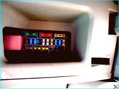
Fig. 1. Relay and fuse box in the passenger compartment
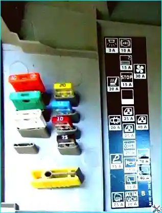
Fig. 2. Fuse box cover inner side
The fuse box is located under the dashboard on the driver's side.
Each fuse protects its own circuit; the fuse allocation is indicated on the fuse box cover.
The fuse box contains blade-type fuses, the colour of which corresponds to the fuse rating.
If any electrical component fails, the condition of the corresponding fuse should be checked first.
A fuse is intact if the metal conductor connecting the contacts is present and unbroken.
To replace a blown fuse, first switch off the relevant electrical circuit, then remove the fuse from its holder using tweezers.
If a newly installed fuse blows immediately when power is applied, check the protected circuit.
If a fuse protects several circuits, connect them one by one to identify the faulty circuit by observing which connection causes the fuse to blow.
The heater and air conditioning draw a high current; therefore, the fuse box is equipped with a circuit breaker to protect their circuits.
If the circuit is opened by the circuit breaker, switch off the heater and air conditioning before pressing the circuit breaker reset button.
A relay is an electronically controlled switch, typically used to:
- switch high currents remotely from the circuit carrying that current, allowing thinner wires and smaller switch contacts to be used;
- provide multiple control inputs, unlike a mechanical switch;
- perform a timer function, for example, to set the interval for the windscreen wipers.
If a circuit controlled by a relay fails and the relay could be the cause, listen to the relay when the system is switched on.
If the relay is working correctly, you should hear a click when it operates.
If the relay is intact, the cause of the fault lies in the components or connecting wires.
If the relay does not work, it means it is not receiving main power, not receiving a control signal, or the relay itself is faulty.
Most relays are mounted in the fuse and relay box located in the engine compartment.
Some specialised relays are mounted separately or in dedicated boxes under the dashboard or in the engine compartment.
Relays
- R — 30 A — Window motor relay
- V — 40 A — Electrical consumers relay
Fuses
- C — 40 A — Passenger compartment blower
- D — 40 A — Rear door one-touch window motors or window motor relay
- E — 20 A — Sunroof motor
- F — 10 A — ABS and stability control ECU
- G — 15 A — Audio system, external display, headlamp washer pump relay, front row cigarette lighter, seat heating elements, windscreen washer pump, diesel fuel heater relay, climate control panel, climate control ECU, electrochromic rear-view mirror, anti-theft alarm, central communication unit
- H — 15 A — Stop lamps
- I — Not used
- J — 25 A — Driver's door window motor
- K — 25 A — Passenger door window motor
- L — 20 A — Electrical consumers cut-off fuse: audio system, external display, exterior mirror switch, anti-theft alarm, instrument panel
- M — 15 A — Horn, diagnostic socket, headlamp washer pump relay, rear wiper motor
- N — 15 A — Rear wiper motor
- O — 20 A — UCH, instrument panel, climate control ECU, auxiliary equipment relay
- T — 20 A — Seat heating elements
- S — 3 A — Interior blower and temperature sensor, electrochromic rear-view mirror, rain and light sensor (depending on specification)
- U — 20 A — Central locking and interior door handle locking system
To access the passenger compartment fuse box:

Fig. 3. Prise the fuse box cover off, overcoming the resistance of the retaining clips
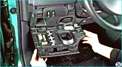
Fig. 4. Open the cover
If necessary, disengage the cover retainers at the bottom and remove the fuse box cover.
The fuse allocation and layout diagram are shown on the inside of the cover.
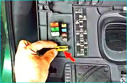
Fig. 5. Using tweezers, remove the fuse
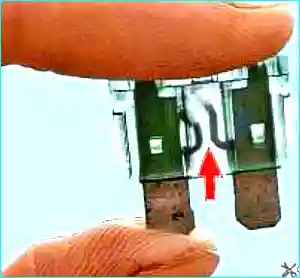
Fig. 6. Appearance of a blown fuse
To access the power fuse box located in the engine compartment:
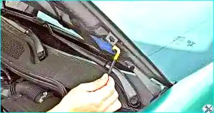
Fig. 7. Open the bonnet
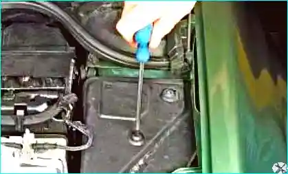
Fig. 8. Unscrew the two screws securing the fuse box cover
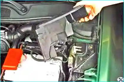
Fig. 9. Remove the cover
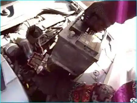
Fig. 10. Remove the battery
Use tweezers to replace the fuses. Install the components in the reverse order.
Removing and installing the fuse boxes
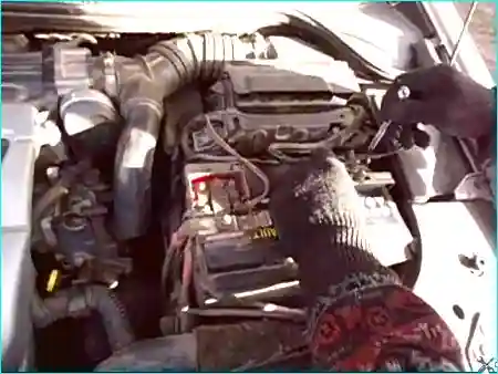
Fig. 11. Disconnect the negative terminal from the battery
Fig. 12. Open the decorative cover of the passenger compartment fuse box
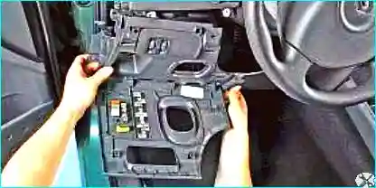
Fig. 13. Remove the lower left and side trims of the dashboard
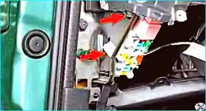
Fig. 14. Release the two retaining clips
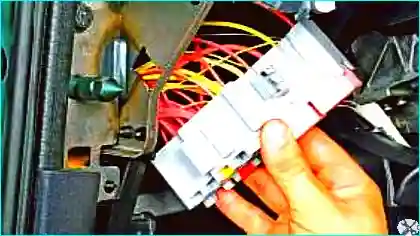
Fig. 15. Remove the fuse box from the amplifier bracket, pulling it out to the length of the wiring
Install the fuse box in the reverse order.
Removing the engine compartment fuse box
Disconnect the negative battery terminal.
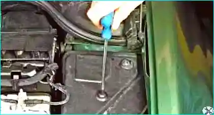
Fig. 16. Unscrew the two screws securing the fuse box cover
Fig. 17. Remove the cover
Remove the battery.
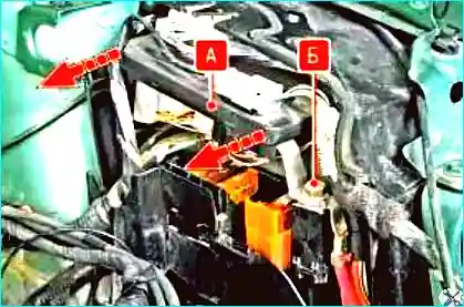
Fig. 18. Unscrew the bolt B securing the communication unit and move unit A aside
Disconnect all wiring harness connectors from the communication unit sockets and remove the unit.
Withdraw the fuse box to the length of the attached wiring.
Install the unit in the reverse order.


