


Summary table of Renault Megane 2 automatic transmission fault codes:
Code - Fault description
- DF002 - ECU
- DF003 - Analogue sensor supply
- DF005 - Oil pressure sensor circuit
- DF008 - Multifunction switch in intermediate position
- DF009 - Multifunction switch in incorrect position
- DF010 - Communication with instrument panel
- DF012 - Solenoid valve supply
- DF016 - Torque converter lock-up solenoid circuit
- DF017 - Oil flow control solenoid circuit to cooler
- DF018 - Torque converter does not lock up
- DF020 - Old oil
- DF023 - Engine oil temperature sensor circuit
- DF024 - Coolant temperature sensor circuit
- DF029 - Multifunction switch in unstable position
- DF036 - Pressure control solenoid circuit
- DF033 - Torque converter turbine speed sensor
- DF048 - Vehicle speed information
- DF049 - Pressure regulation
- DF055 - Injection system ECU; Instrument panel
- DF064 - Display circuit
- DF085 - Shift sequence solenoid circuit No. 1
- DF086 - Shift sequence solenoid circuit No. 2
- DF087 - Shift sequence solenoid circuit No. 3
- DF088 - Shift sequence solenoid circuit No. 5
- DF089 - Shift sequence solenoid circuit No. 4
- DF093 - Manual control pulse switch circuits
- DF095 - Selector lever lock solenoid circuit
- DF109 - Engine torque information via multiplex network
- DF112 - Shift sequence solenoid circuit No. 6
- DF114 - Pedal position information via multiplex network
- DF116 - Engine crankshaft speed information via multiplex network
- DF117 - Transmission of left rear wheel speed information via multiplex network
- DF118 - Transmission of right rear wheel speed information via multiplex network
- DF119 - Brake pedal position
- DF122 - Communication with UCH
- DF123 - Communication with ABS ECU
- DF126 - Torque converter turbine speed information
- DF129 - Vehicle stability control (ESP)
- DF131 - Wheelspin
- DF174 - ABS fault detected
- DF175 - Left front wheel speed information via multiplex network
- DF176 - Right front wheel speed information via multiplex network
- DF177 - Automatic transmission overheating
The modular diagnostic connector is shown in Figure 1.
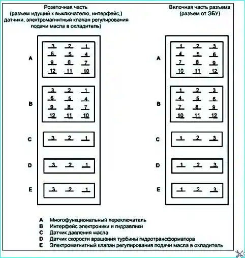
Fig. 1. Modular diagnostic connector


