


On Renault Megane 2 vehicles, headlamp units are used that combine the dipped and main beam headlights and the direction indicators.
In addition, the headlamps contain the side light bulbs.
The dipped and main beams are switched on by the left steering column stalk switch for the exterior lighting, via relays.
Control voltage is supplied to the relay coils for the main beam lamps from the exterior lighting switch when it is in the headlights-on position.
Regardless of the position of the exterior lighting switch, the main beam can be flashed by pulling the stalk switch towards you.
To replace the headlamp unit, disconnect the negative battery terminal.
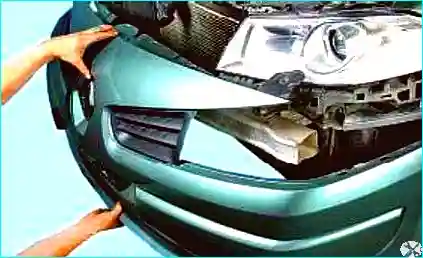
Fig. 1. Remove the front bumper
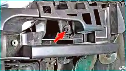
Fig. 2. Unscrew the lower outer screw
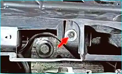
Fig. 3. Unscrew the lower inner screw securing the headlamp unit
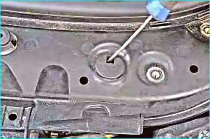
Fig. 4. Prise out the upper retaining clip of the headlamp unit
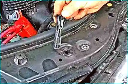
Fig. 5. Remove the clip from the hole in the upper radiator frame
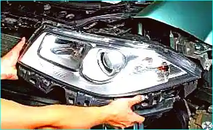
Fig. 6. Withdraw the headlamp unit as far as the connected wiring allows
Release the wiring harness connector clip.
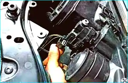
Fig. 7. Disconnect the connector from the headlamp leveller motor
Release the wiring harness connector clip.
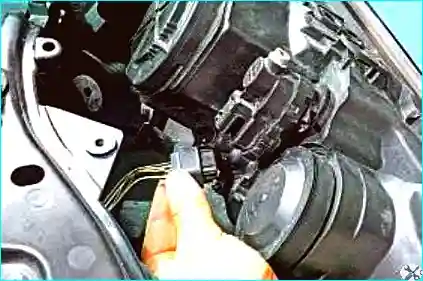
Fig. 8. Disconnect the connector from the headlamp unit
Remove the headlamp unit.
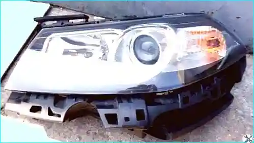
Fig. 9. Install in the reverse order
Automatic switching on of exterior lighting when stationary (guide-me-home lighting):
Depending on the specification, vehicles are equipped with an automatic dipped beam switching system (with the engine off) to illuminate the area in front of the vehicle.
This function is only active with the ignition off, the exterior lighting switch in the neutral position, the indicators and fog lights off, the side lights off, and during 30-second intervals (no more than two minutes in total).
Activation:
The function is activated using the stalk switch for the indicators, exterior lighting and fog lights:
- move the card in the reader to the first detent position;
- flash the main beam by operating the stalk switch;
- the dipped beam comes on for 30 s.
Each time the alarm is deactivated with the main beam, the dipped beam duration is extended by 30 s (up to a maximum of two minutes in total).
This function is deactivated when the side lights or ignition are switched on.
Automatic switching on of exterior lighting while driving:
This function is activated or deactivated using the exterior lighting, indicator and fog light switch, provided the UCH is correctly configured.
With the engine stopped or the vehicle stationary with the engine running, press and hold the «Auto» switch on the end of the exterior lighting, indicator and fog light stalk.
When the state changes, the instrument panel emits an audible signal and a corresponding message appears.
From this point on, the system operates in automatic mode.
To return to manual mode, repeat the same operation.
Headlamp beam adjustment with halogen bulbs:
Use this method only for halogen bulbs; for gas discharge bulbs, use an optical test rig.
Check the tyre pressures.
Position the vehicle perpendicular to a smooth wall at a distance of three metres.
An assistant or a 75 kg load should be placed on the driver's seat.
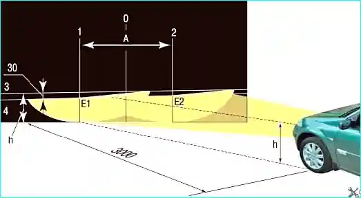
Fig. 10. Mark out the screen on the wall as shown in the figure
The longitudinal plane of symmetry of the vehicle must pass through line 0 on the screen.
The distance «A» between lines 1 and 2 must be equal to the distance between the centres of the dipped beam bulbs.
Rock the vehicle from the side to allow the suspension springs to settle.
Measure the height of the headlamp centres from the ground on your vehicle. This will be the distance «h» on the screen.
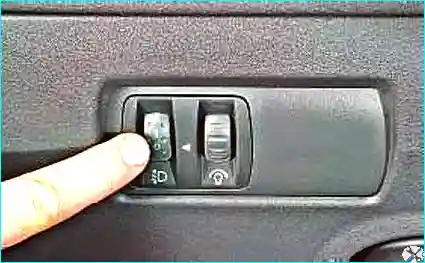
Fig. 11. Set the electric headlamp leveller control on the dashboard to the position corresponding to the vehicle load with one driver
Switch on the dipped beam.
Adjust the direction of the light beam for each headlamp individually. Cover the other headlamp.
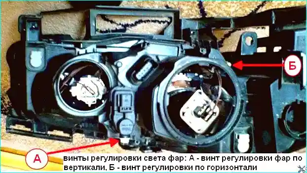
Fig. 12. Headlamp adjusting screws: A - vertical beam adjusting screw, B - horizontal adjusting screw
Open the bonnet and, by turning the adjusting screws, adjust the position of the light beam for each headlamp, first horizontally and then vertically.
The headlamps are considered correctly adjusted when the upper limits of the left-hand parts of the beams coincide with line 4, and the vertical lines 1 and 2 pass through points E1 and E2, the intersections of the horizontal and inclined sections of the beams.
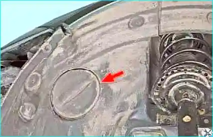
Fig. 13. Access panel to the headlamp unit
To access the horizontal adjusting screw, use a 6 mm hexagon key, inserting it through the access panel in the wheel arch.
Replacing the halogen headlamp bulbs
The bulb replacement methods differ depending on the engine fitted:
- through the access panel in the wheel arch (fig. 4);
- through the engine compartment.
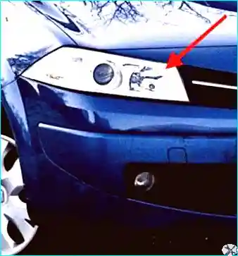
Fig. 14. Replacing the dipped and side light bulb
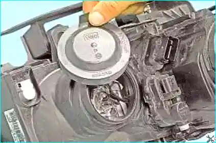
Fig. 15. Remove the dipped beam bulb cover
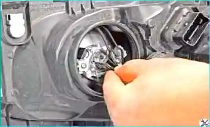
Fig. 16. Disconnect the wiring connector from the bulb base
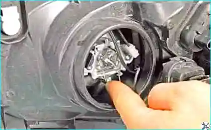
Fig. 17. Release the spring retainer
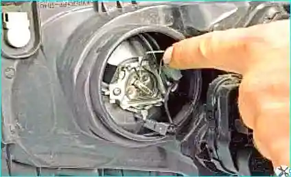
Fig. 18. Remove the spring retainer from the groove of the bulb base
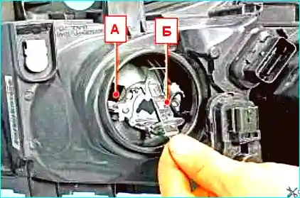
Fig. 19. Remove the dipped beam bulb «B» or the side light bulb «A»
Install the new bulb in the reflector and secure it with the retainer.
Replacing the main beam bulb
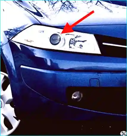
Fig. 20. To replace the bulb, perform the following operations
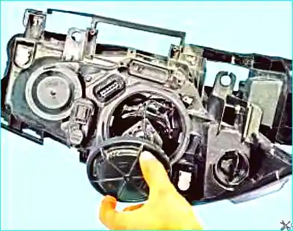
Fig. 21. Turn the main beam bulb cover a quarter turn anti-clockwise and remove it
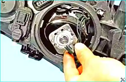
Fig. 22. Disconnect the wiring connector from the main beam bulb base
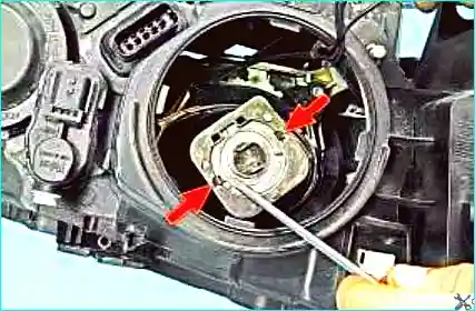
Fig. 23. Prise out the bulb base holder
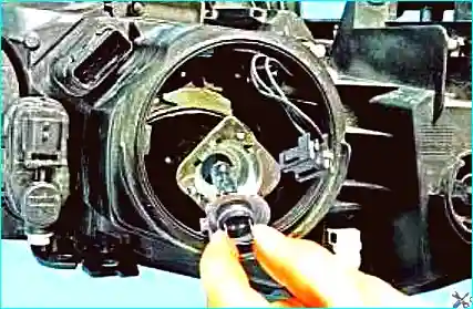
Fig. 24. Remove the bulb
Install the new bulb in the reflector and secure it with the holder.
Replacing the direction indicator bulb
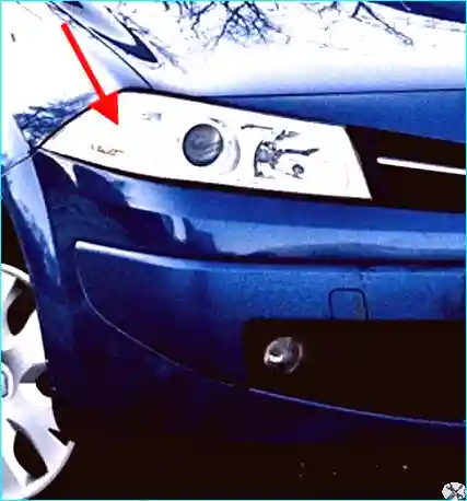
Fig. 25. The front direction indicator bulb is replaced as follows
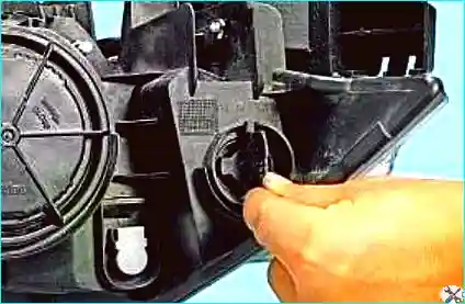
Fig. 26. Turn the indicator bulb holder a quarter turn anti-clockwise
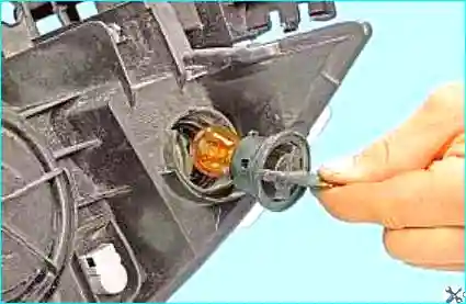
Fig. 27. Remove the holder with the bulb from the headlamp unit
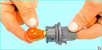
Fig. 28. Pressing on the bulb, turn it anti-clockwise
Remove the bulb from the holder.
Install the new bulb in the holder, then the holder in the headlamp unit.
Replacing the side repeater bulb
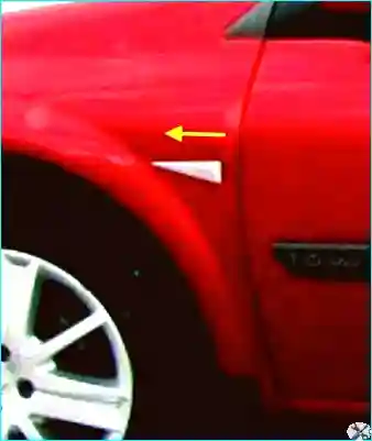
Fig. 29. To replace the side indicator bulb, slide the side indicator in the direction of the arrow in the figure
Remove the side indicator from the wing aperture of the vehicle.
Remove the holder from the repeater and remove the capless bulb from the holder.
Install the bulb and repeater in the reverse order.


