


The Renault Megane 2 is equipped with an electric power steering system.
The steering is adjustable for reach and rake.
The steering gear is of the rack-and-pinion type.
The electronic control unit is the controlling device in the electric power steering system.
Based on information received from the wheel speed sensors, vehicle speed sensor and steering wheel angle sensor, the control unit activates the electric motor to provide additional torque at the steering wheel.
The vehicle's steering system consists of the steering wheel, the steering column (on which the power assist unit is mounted), the steering gear, two tie rods with track rod ends, connected by ball joints to the front suspension steering knuckles.
The electric power steering system, in addition to the electronic control unit, includes sensors, actuators, connectors and fuses.
The control unit is connected by wiring to all sensors in the system.
The control unit determines the direction and amount of additional assistance based on the vehicle speed and signals from the torque and steering angle sensors.
As a result, the control unit varies the steering assistance according to vehicle speed: the lower the speed, the greater the assistance; conversely, at high speed the assistance is minimal.
This characteristic provides light manoeuvrability at low speeds and good steering feel at higher speeds.
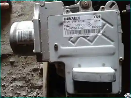
Fig. 1. The electric power steering control unit, mounted on the steering column, detects faults in the system, identifies and stores the fault codes
The control unit switches the system to fail-safe mode, disabling the electric power assist.
The torque sensor measures the amount of twist in the steering shaft and converts it into an electrical signal sent to the control unit.
The torque sensor is integrated into the control unit.
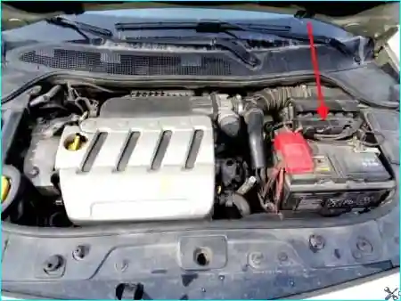
Fig. 2. The engine control unit transmits engine speed data to the electric power steering control unit
The electric motor of the power steering unit, mounted on the steering column, generates additional torque when voltage is applied to it on command from the control unit.
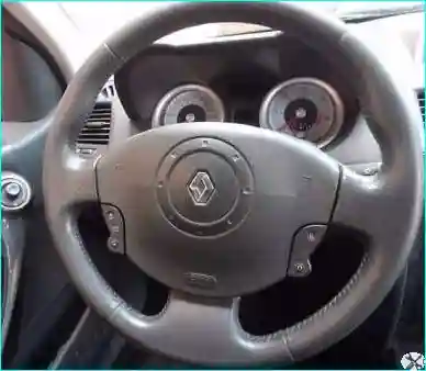
Fig. 3. The steering wheel incorporates the airbag and horn switch, and may also be equipped with audio system and cruise control controls depending on the specification
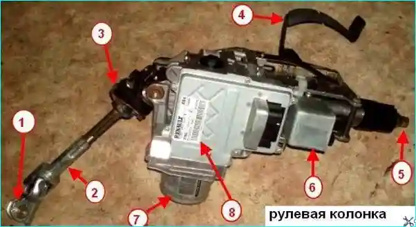
Fig. 4. Steering column: 1 — lower universal joint of the intermediate shaft; 2 — intermediate shaft; 3 — upper universal joint of the intermediate shaft; 4 — steering column adjustment lever; 5 — steering shaft; 6 — steering lock electromechanical mechanism; 7 — electric power steering motor; 8 — electric power steering control unit
The steering column (Fig. 4) is adjustable for reach and rake using the adjustment lever 4.
The steering column is equipped with the control unit 8, which manages the motor 7.
The steering column is also equipped with the electromechanical steering lock 6 of the anti-theft device, which locks the steering shaft 5.
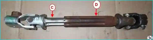
Fig. 5. The steering intermediate shaft connects the steering shaft and the steering gear pinion shaft via universal joints
The intermediate shaft consists of two parts: upper C and lower D.
In a frontal impact, the upper part collapses into the lower part, reducing the length of the intermediate shaft and thereby reducing the risk of injury to the driver.
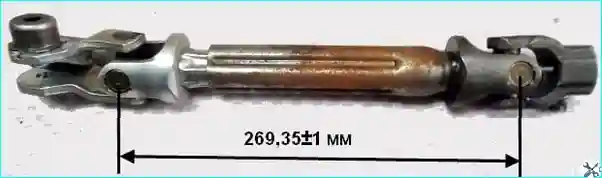
Fig. 6. Measuring the length of the intermediate shaft
Note:
If it is not possible to install the eccentric bolt on the universal joint, for example after an impact, the shaft length must be checked.
If the shaft length does not correspond to 269.35 ± 1 mm, replace the complete steering column assembly.
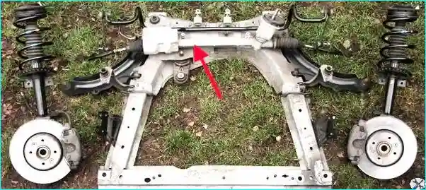
Fig. 7. The steering gear is secured to the front suspension subframe
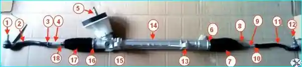
Fig. 8. Steering gear: 1, 12 — track rod end ball joints; 2, 11 — track rod ends; 3, 10 — track rod end locknuts; 4, 9 — tie rods; 5 — steering gear pinion shaft; 6, 16 — inner boot clips; 7, 17 — dust boots; 8, 18 — outer boot clips; 13, 15 — steering gear mounting brackets; 14 — rack housing
The tie rods 4 and 9 (Fig. 8) are attached to the steering rack via ball joints.
The track rod ends 2 and 11 are connected by ball joints to the front suspension steering knuckles.


