Removal of the fuel pump module

Disconnect the cables from the battery terminals, starting with the negative terminal.

Lift the rear seat cushion.

Remove the mat retainer.

Unscrew the mat.
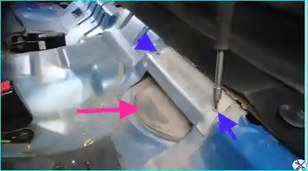
Removing the access cover
Fig. 1. Unscrew the cover mounting bolts

Remove the cover and the access hole plug.

Remove the access hole plug with a screwdriver by prying at the edge.
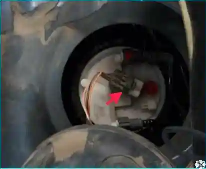
Disconnecting the wiring connector
Fig. 2. Disconnect the wiring connector
Disconnecting the fuel lines
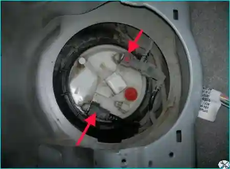
Fig. 3. Pressing the clips, disconnect the fuel supply and return lines
Unscrewing the retaining nut
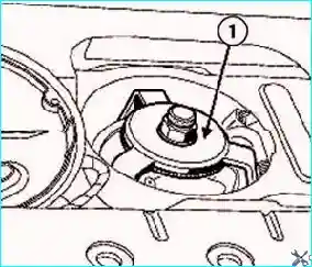
Fig. 4. Unscrew the plastic retaining nut of the fuel module using the tool (Mot. 1397)
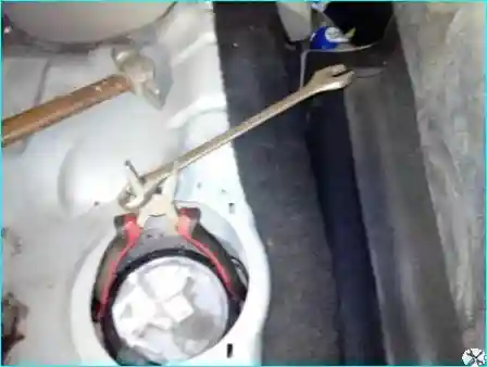
Unscrewing the nut with pliers
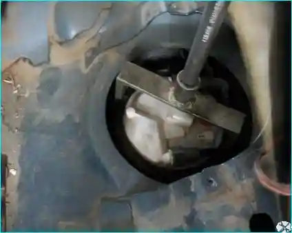
Fig. 5. In roadside conditions, it can be unscrewed this way with pliers and an open-end wrench
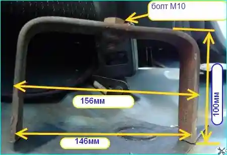
Homemade tool
Fig. 6. At home, a tool can be made from a strip of metal 3–5 mm thick by welding a bolt to it
Using the homemade tool
Fig. 7. Using this tool, unscrew the fuel module retaining nut
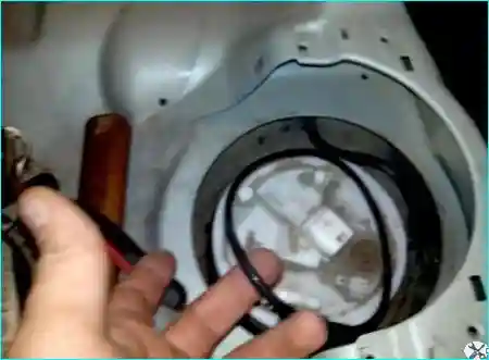
Removing the module
Fig. 8. After unscrewing the plastic retaining nut, carefully remove the module and the rubber O-ring

Take care not to damage the float.
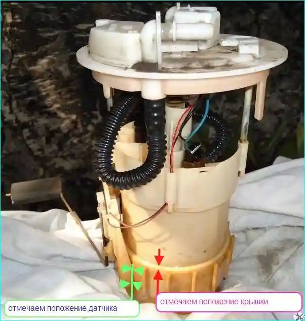
Marking the module
Fig. 9. Using a marker or a sharpened screwdriver, mark the position of the fuel level sensor and the position of the lower module cover

This is to ensure the correct position of the fuel level sensor.
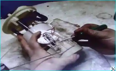
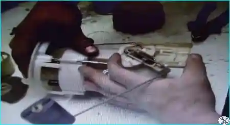
Prying the clip
Fig. 10. Pry the plastic clip with a screwdriver
Removing the fuel level sensor
Fig. 11. Remove the fuel level sensor
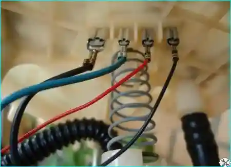
Position of the contacts
Fig. 12. Position of the contacts
Separating the cover and body
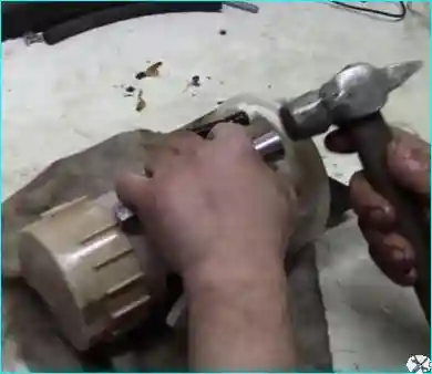
Fig. 13. Place the module on its side and separate the cover from the module body with light taps

The cover can also be separated using several screwdrivers inserted into the cover connector at small intervals.
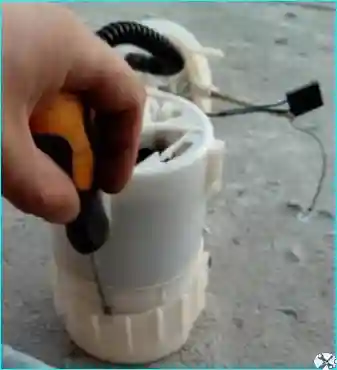
Installing the new filter
Fig. 14. Install the new filter and reassemble in the reverse order

The electric pump is compatible with some domestic vehicles.

When replacing the pump, take into account its flow rate.

To avoid the risk of deforming the tank, refit the retaining nut of the fuel pump assembly with fuel level sensor and fuel filter immediately after removing this assembly.

Installation

Replace the O-ring.
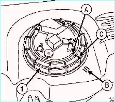
Installing the fuel pump assembly
Fig. 15. Installation of the «fuel pump – fuel level sensor - fuel filter» assembly: 1 - nut; A, B, C - marks

Install the «fuel pump - fuel level sensor - fuel filter» assembly, aligning mark «A» on this assembly with mark «B» on the fuel tank (see Fig. 15).

Screw on the nut.

Tighten the nut until mark «C» on the nut aligns with mark «B» on the fuel tank and with mark «avec» on the fuel pump assembly with fuel level sensor and fuel filter (Fig. 15).

Install the remaining equipment in the reverse order of removal.

Connect the cables to the battery terminals, starting with the positive terminal.