


Most electrical equipment supply circuits in the vehicle are protected by fuses.
High-current consumers are connected via relays.
The fuses and relays are installed in fuse boxes located in the passenger compartment under the dashboard on the right-hand side, and in the engine compartment next to the battery.
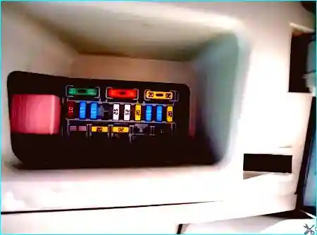
The location of the fuses and relays may vary depending on the vehicle specification.
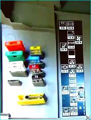
The fuse box is located in the passenger compartment, in the lower left part of the dashboard (see Fig. 2).
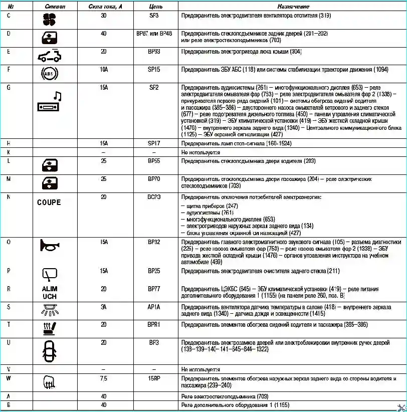
The assignment of fuses and relays (depending on the vehicle specification) is given in Table 1.
Relay box (1173)
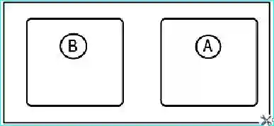
The relay box is located in the dashboard, to the left of the interior blower motor.
Single relay (1524)
The relay is mounted on the accelerator pedal bracket.

The relay assignment (depending on the vehicle specification) is given in Tables 2 and 3.
Table 2. Relay assignment (depending on vehicle specification)
- A — Rated current 40 A — Additional heating relay 330 W (1067);
- B — Rated current 70 A — Additional heating relay 660 W (1068).
Table 3. Contact and circuit assignment (depending on vehicle specification)
- Rated current 40 A — Stop lamp relay (1524), controlled by the stability control system ECU (1094).
Body computer (645)
The unit is located in the passenger compartment, in the lower left part of the dashboard.
Contact – Circuit – Assignment
PE1 (40-pin brown connector)
- 1 - 26I - Control «-» of the safety system stroke sensor
- 2 - 47z - Outside temperature signal / display
- 3 - 64F - Control «I» of the hazard warning lamp
- 4 - 26EC - Control of the card presence LED in the reader
- 5 - 26K - Signal «-» of the clutch pedal stroke sensor
- 6 - 20AW - Pulse control for locking/unlocking door locks
- 7 - 26N - Signal «+» of engine start/stop
- 8 - 87T - Signal of the door lock switch
- 9 - 20T - Control «-» of the child safety system LED
- 10 - Not used
- 11 - 20AL - Control of locking rear door locks from inside
- 12 - 16A - Control «+» of the windscreen washer pump motor
- 13 - 26M - Control of the «engine running» warning lamp
- 14 - 20M - Door locking LED
- 15 - 87G - Signal «-» of the passenger door switch
- 16 - 87B - Signal «-» of the right rear door switch
- 17 - 87H - Signal «-» of the driver's door switch
- 18 - 20BG - Status signal of the rear door interior handle locking system
- 19 - 87A - Signal «-» of the left rear door switch
PP2 (12-pin black connector)
- 1 - 261 - «-» to the steering column electric lock
- 2 - APCB - «-» after ignition switch via fuse / Fuse of the steering column lock closing contact
- 3 - 36A - Control «+» of the rear window wiper motor
- 4 - BP25 - «-» battery to the rear window wiper motor via fuse
- 5 - 20BH - Control of locking the driver's door lock and fuel filler flap
- 6 - 20BC - Control of unlocking the driver's door lock and fuel filler flap
- 7 - 20BK - Control of locking the front and rear passenger door locks
- 8 - 20BD - Control of unlocking the front and rear passenger door locks
- 9 - BP3 - «-» battery via fuse to door electric locks
- 10 - 20X - Control of locking the front interior door handles
- 11 - 20W - Control of locking the rear interior door handles
The contact and circuit assignment (depending on vehicle specification) is given in Table 4.
Protection and switching box (1337)
The box is located in the engine switching box (in the engine compartment).
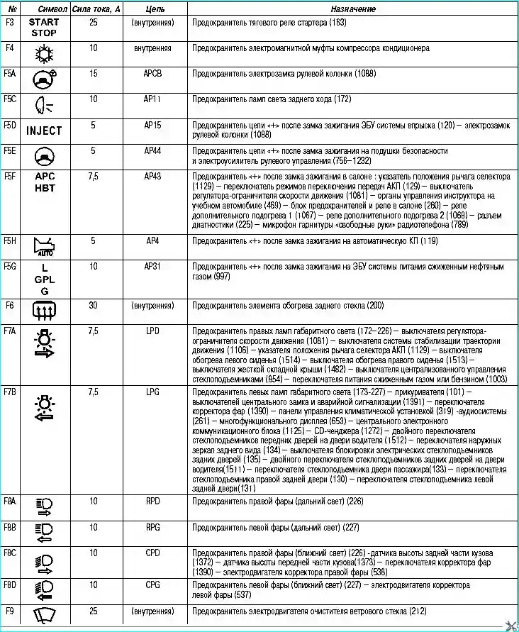
The designation of the fuses in the protection and switching box is shown in Fig. 7.
The circuits protected by fuses (depending on vehicle specification) are given in Table 7.
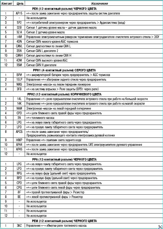
The box located in the engine switching box (in the engine compartment) see Fig. 6.
The contact and circuit assignment (depending on vehicle specification) is given in Table 6.
Table 5. Circuits protected by fuses (depending on vehicle specification)
Table 6. Contact and circuit assignment (depending on vehicle specification)
Power supply circuit fuse box (777)
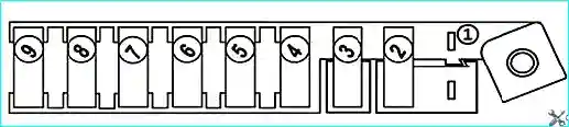
The fuse assignment (depending on vehicle specification) is given in Table 7.
Table 7. Fuse assignment (depending on vehicle specification)
- F1 — Not used
- F2 — 70 A — BP35 — Pre-heating ECU fuse (257)
- F3 — 20 A — BP27 — Fuel filter heater relay fuse (450) on F9Q engine
- F4 — 70 A — BP12 — Passenger compartment fuse and relay box fuse (260)
- F5 — 50 A — BP8 — ABS ECU fuse (118-1094)
- F6 — 70 A — BP81 — Electric power steering fuse (1232)
- F7 — 40 A — BP9 — Additional heating relay 1 fuse (1067)
- F8 — 60 A — BP11 — Passenger compartment fuse and relay box fuse (260)
- F9 — 70 A — BP91 — Additional heating relay 2 fuse (1068)
Battery positive circuit protection fuse box (1033)
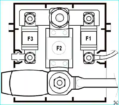
Table 8. Fuse assignment (depending on vehicle specification)
- F1 — 30 A — BPS1 — Battery «+» circuit fuse with passenger compartment fuse and relay box fuse (260) — Body computer (645).
- F2 — 350 A; 400 A — BPDA — Battery «+» fuse via fuse to starter (163), alternator (103), power supply circuit fuse box (777), protection and switching box (1337). Rated current: 350 A on petrol engine vehicles, 400 A on diesel engine vehicles.
- F3 — 30 A — BP31 — «+» fuse via fuse to engine systems through the protection and switching box (1337).
Relay box (1337)
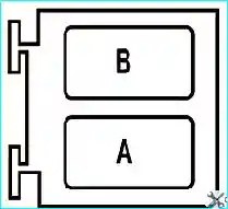
The box is located in the engine compartment switching box under the protection and switching box (1337) (Fig. 10).
The relay assignment (depending on vehicle specification) is given in Table 9.
Table 9. Relay assignment (depending on vehicle specification)
- A — Rated current 20 A — Headlight washer motor relay (753);
- B — Rated current 20 A — Headlight washer motor relay (1338).
Relay box (299)
The box is located in the engine compartment switching box under the protection and switching box (1337) (Fig. 10).
The relay assignment (depending on vehicle specification) is given in Table 10.
Table 10. Relay assignment (depending on vehicle specification)
- A — Rated current 20 A — Diesel fuel heater relay (450);
- B — Not used.
LPG fuel system relay boxes (299)
The box is located in the engine compartment switching box under the protection and switching box (1337) (Fig. 11).
The relay assignment (K4M764 engine, depending on vehicle specification) is given in Table 11.
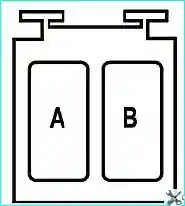
The relay assignment (K4M764 engine, depending on vehicle specification) is given in Table 12.
Table 11. Relay assignment (K4M764 engine, depending on vehicle specification)
- A — Rated current 20 A — Fuel pump relay (236);
- B — Rated current 20 A — Fuel pump cut-off relay on LPG vehicles (1196).
Table 12. Relay assignment (K4M764 engine, depending on vehicle specification)
- A — Rated current 20 A — LPG system solenoid valve relay (1259);
- B — Rated current 20 A — LPG cylinder relay (1457).


