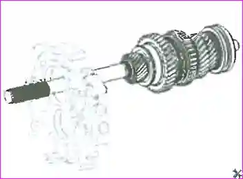
1. Remove the clutch release bearing, clutch release fork, clutch housing, front cover components, input shaft, front intermediate shaft bearing snap ring, control lever assembly and gearbox cover with the gear shift mechanism.
Materials used and precautions:
- To drive out the pins, use a drift punch less than 5 mm in diameter.
- Take care not to lose the needle bearings, steel balls or detent springs.
- Before disassembly, clean the external surfaces of the gearbox.
- Place the removed parts on a clean surface; keep small items (balls, pins, snap rings) in a separate container.
- When removing the shift forks and shafts, mark them for correct subsequent installation.
Disassembly procedure
1. Removal of the clutch assemblies and the front part of the gearbox
Remove the clutch release bearing, clutch release fork, clutch housing, front cover components, input shaft, front intermediate shaft bearing snap ring, control lever assembly and gearbox cover with the gear shift mechanism.
Remove the positioning mechanism components, the rear case assembly (steel ball, spring and shift shaft set bolt) and the gearbox case.
2. Loosening the threaded plugs of the fork shafts
Loosen the threaded set plug of each shift fork shaft, remove the spring and the steel ball.
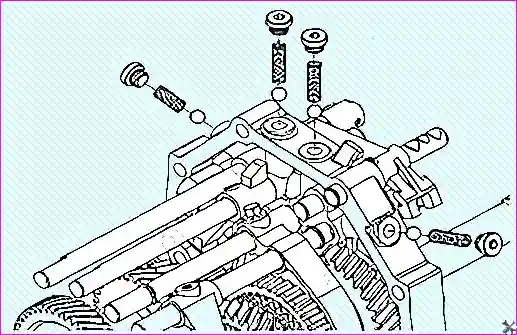
3. Removal of the shift fork retaining pins
Remove the retaining pin of each shift fork, the elastic cylindrical pin, the set screws and the snap ring.
Note: to remove the pins, use a drift punch less than 5 mm in diameter.
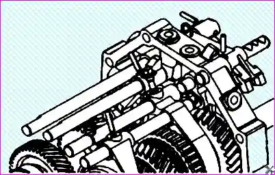
4. Removal of the fifth/reverse shift fork and shaft
Remove the fifth/reverse shift fork, the fifth gear fork shaft and the fifth gear fork.
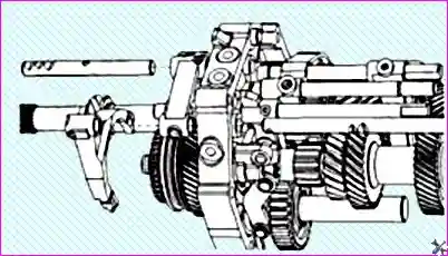
5. Extraction of the detent balls and removal of the guide block
Extract the steel detent balls from the fifth/reverse guide block, remove the fifth/reverse guide block, the reverse fork shaft and the reverse block, then extract the reverse lock mechanism guide rod from the reverse fork shaft.
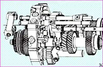
6. Extraction of the lock pin and removal of the first/second fork shaft
Extract the lock mechanism pin, remove the first/second gear fork shaft and extract the first/second lock mechanism guide rod.
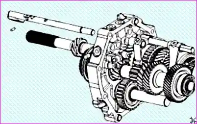
7. Removal of the rear snap ring and fifth gear
Remove the rear intermediate shaft snap ring, the fifth gear connecting gear, the fifth gear, the fifth gear needle bearing, the fifth gear thrust washer and the steel ball (Ø 6.35 mm).
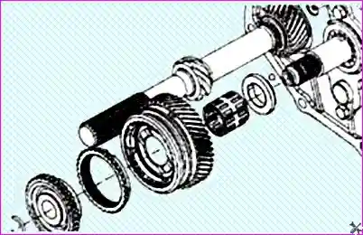
8. Removal of the speedometer gear and support baffle
Remove the speedometer drive gear snap ring, the speedometer drive gear, the output shaft rear support baffle and the output shaft rear bearing snap ring.
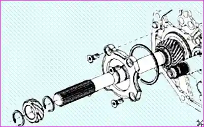
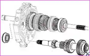
9. Removal of the intermediate shaft assembly
Remove the gearbox intermediate shaft assembly and its bearing.
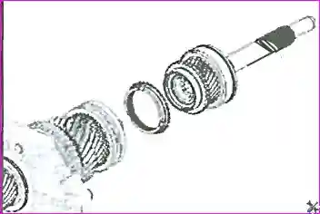
10. Removal of the input shaft assembly
Remove the gearbox input shaft assembly and the third/fourth synchroniser ring.
Note: take care not to lose the gearbox input shaft needle bearing.
11. Removal of the output shaft assembly
Remove the output shaft assembly.