


Position the vehicle on an inspection pit or a vehicle lift. Secure the rear wheels with wheel chocks.
Remove the wheel trim and loosen the fixing nuts.
Raise the front of the vehicle and place a robust support under the lower suspension arm to simulate the working load.
Remove the front wheel.

Holding the shock absorber rod with a 7 mm spanner, unscrew the upper mounting nut. Remove the upper washer and rubber bushing from the rod.

Unscrew the two nuts securing the lower shock absorber joint to the bracket.
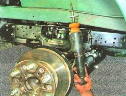
Carefully extract the shock absorber downwards, guiding it through the hole in the lower arm.

Install the new shock absorber in the reverse order. Important: Tightening torque for the lower nut: 40–60 N·m, upper rod nut: 15–20 N·m.
Replacing the stabiliser bar
Required tools: 17 mm and 19 mm spanners, 14 mm socket.
Secure the rear wheels with wheel chocks and apply the parking brake.
Loosen the front wheel nuts, raise the front of the vehicle, support it on robust stands, and remove the wheels.
⚠️ Important: It is strictly forbidden to dismantle the stabiliser with only one side of the vehicle raised. The twisted bar, upon release, can cause serious injury!
For better access, remove the engine splash guard.

Unscrew the bolts securing the stabiliser bushing clamps to the lower arms and remove the clamps.

Unscrew the nuts securing the stabiliser bar to the suspension crossmember and remove the bar.
Remove the old rubber bushings from the bar and clean the surface of dirt.
Check the condition of the bar:
- — If slightly deformed (the ends are not in the same plane), the bar must be carefully straightened.
- — If significantly deformed or cracked, the bar must be replaced.
Replace the rubber bushings (it is recommended to lubricate them with soapy water during installation to prevent squeaking) and install the stabiliser in the reverse order. Tightening torque for the bar nuts: 40–50 N·m, clamp bolts: 20–30 N·m.