


General information on engines
Renault Megane 2 vehicles are equipped with K4J (1.4 L), K4M (1.6 L), F4R (2.0 L) engines and the K9K dCi (1.5 L) diesel engine. This article examines the design features of the K4J (1.4 L), K4M (1.6 L) and F4R (2.0 L) engines.
General characteristics: petrol engines, four-stroke, four-cylinder, in-line, sixteen-valve — with twin overhead camshafts. The engines are mounted transversely in the engine bay. Their design is similar. The main differences relate to component dimensions.
Powertrain layout
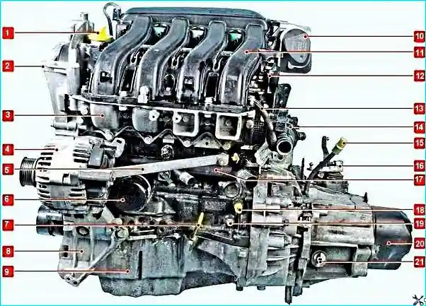
1 — oil filler cap; 2 — upper timing belt cover; 3 — intake pipe; 4 — alternator;
5 — alternator mounting bracket; 6 — oil filter; 7 — oil level dipstick; 8 — air conditioning compressor bracket;
9 — lower oil sump; 10 — throttle body; 11 — receiver; 12 — lifting eye;
13 — injector wiring harness; 14 — water distributor; 15 — gearbox oil level dipstick;
16 — gear selector mechanism; 17 — cooling system hose; 18 — knock sensor;
19 — TDC timing hole plug; 20 — rear gearbox cover; 21 — gearbox filler plug
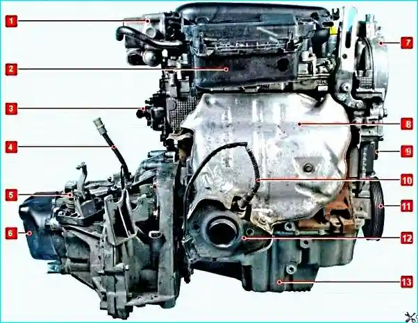
1 — throttle body; 2 — receiver; 3 — water distributor; 4 — gearbox oil dipstick guide;
5 — gear selector mechanism; 6 — rear gearbox cover; 7 — upper timing belt cover; 8 — upper exhaust manifold heat shield;
9 — lower timing belt cover; 10 — upstream oxygen sensor; 11 — auxiliary drive belt pulley;
12 — exhaust manifold; 13 — lower oil sump
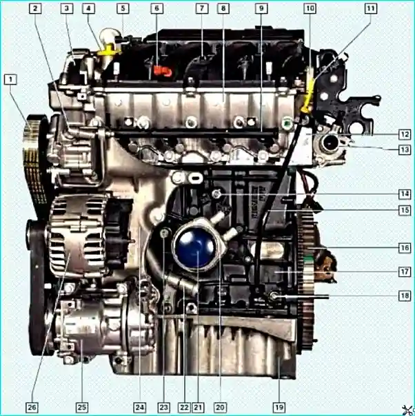
1 — auxiliary drive belt; 2 — power steering pump; 3 — timing belt; 4 — oil filler cap;
5 — manifold absolute pressure sensor; 6 — intake air temperature sensor; 7 — receiver; 8 — intake pipe;
9 — fuel rail with injectors; 10 — cylinder head cover; 11 — oil level dipstick;
12 — cylinder head; 13 — thermostat; 14 — knock sensor; 15 — oil dipstick guide;
16 — flywheel; 17 — cylinder block; 18 — plug; 19 — oil sump; 20 — heat exchanger; 21 — oil filter;
22 — coolant pump feed pipe; 23 — oil pressure sensor; 24 — ancillary bracket;
25 — air conditioning compressor; 26 — alternator
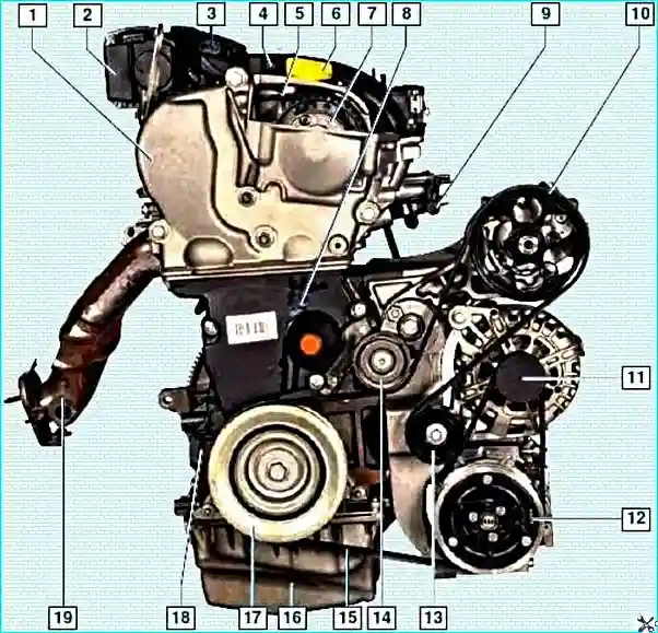
1 — upper timing cover; 2 — throttle body; 3 — manifold absolute pressure sensor; 4 — receiver;
5 — timing belt; 6 — oil filler cap; 7 — dephaser; 8 — lower timing cover;
9 — fuel rail; 10 — power steering pump pulley; 11 — alternator pulley; 12 — air conditioning compressor electromagnetic clutch;
13 — idler roller; 14 — tensioner roller; 15 — auxiliary drive belt; 16 — oil sump;
17 — auxiliary drive pulley; 18 — cylinder block; 19 — exhaust manifold
Firing order: 1-3-4-2, counted from the flywheel.
Fuel system: sequential multi-point fuel injection.
The engine, gearbox and clutch form a powertrain mounted on three rubber-metal mounts.
Variable valve timing system (F4R engine)
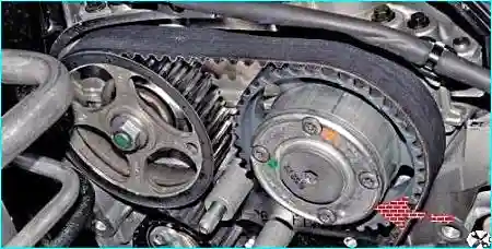
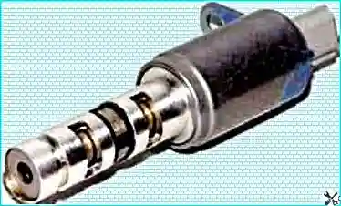
Dephaser operating principle: the system sets optimum valve timing for every operating point to increase power and driveability by altering the intake camshaft position. It is controlled by the engine control unit (ECU).
Dephaser operating modes:
- Below 1450 rpm — no voltage to the solenoid valve (closed).
- Between 1450 and 4300 rpm with the accelerator fully depressed — the ECU applies voltage (valve open).
- Above 4300 rpm — valve supply is cut.
Important! The variable valve timing components (solenoid valve and camshaft phasing mechanism) are precision-made assemblies. During repair, only replacement of the components as a complete unit is permitted.
Cylinder block and crankshaft
The cylinder block is cast from cast iron, with the cylinders bored directly in the block. The lower part has five main bearing supports with detachable caps. The caps are not interchangeable.
The crankshaft has five main and four big-end journals. The main and big-end bearing shells are steel, thin-walled.
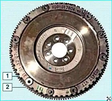
The flywheel is cast iron, mounted on the clutch cover and secured by six bolts. On automatic models a torque converter drive plate is fitted instead of the flywheel.
Cylinder head and valve gear
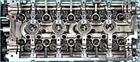
The cylinder head is cast from aluminium alloy, common to all four cylinders. It is secured by ten bolts. A non-settling metal gasket is fitted between block and head.
The valves are steel, arranged in a V, two inlet and two exhaust per cylinder. The inlet valve head is larger than the exhaust.
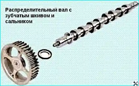
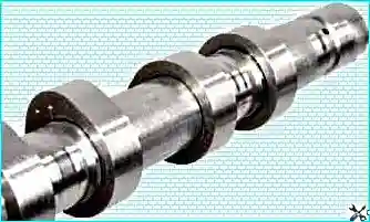
The camshafts — one operates the inlet valves, the other the exhaust valves. Each shaft has eight cams. The bearings (six per shaft) are split.
Note: the camshaft pulley is not keyed or pinned to the shaft; it is held only by friction when the nut is tightened.
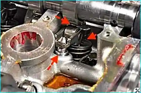
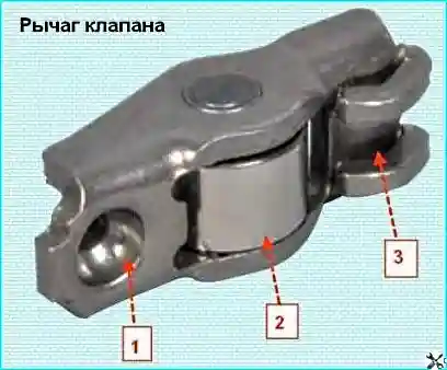
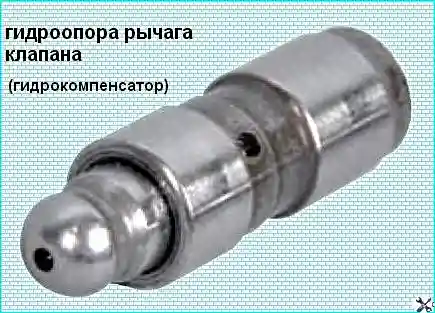
Hydraulic tappets automatically maintain zero-clearance contact between the cam and the rocker roller, compensating for wear.
Lubrication system
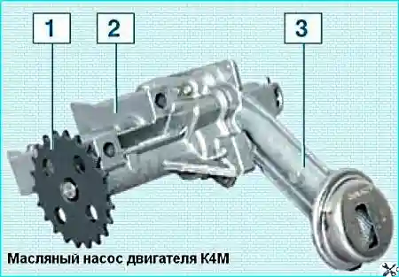
Lubrication is combined. Oil is pressure-fed to the main and big-end bearings, camshaft bearings and hydraulic tappets.
The oil pump is a gear pump located in the sump, chain-driven from the crankshaft.
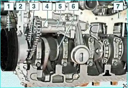
Important! The pump drive sprocket is clamped between the timing pulley and the crankshaft shoulder. If the pulley bolt is loose, the sprocket may slip, causing oil pressure loss.
Crankcase ventilation system
The crankcase ventilation system is closed and forced. Blow-by gases pass through an oil separator in the cam cover, are cleaned, then flow via the air filter housing, throttle body, receiver and intake pipe into the cylinders.
Possible engine faults
Engine will not start:
- No fuel pressure in the rail: blocked pipes, faulty pump, blocked filter, faulty pressure regulator.
- Ignition system faulty — carry out diagnosis.
2. Engine lacks full power
- Throttle position sensor faulty — replace throttle body assembly.
- Insufficient fuel rail pressure.
- Air filter dirty — replace filter element.
- Low compression (below 10 kg/cm²): blown head gasket, burnt pistons, broken rings, poor valve seating, worn bores.
3. Unstable idle
- Insufficient fuel pressure.
- Air leak via brake servo hose.
- Ignition system faulty.
4. Low oil pressure when hot
- Poor quality or diluted oil — change oil.
- Oil pump dirty or worn.
- Oil filter blocked.
- Strainer loose or blocked.
- Excessive crankshaft bearing clearance.
5. Main bearing knock (dull, metallic)
- Excessive crankshaft end-float — replace thrust washers.
- Low oil pressure.
- Excessive shell-to-journal clearance.
6. Big-end bearing knock (sharper than main)
- Excessive big-end clearance — replace shells, regrind journals.
7. Piston slap (dull, muffled)
- Excessive piston-to-bore clearance — replace pistons, rebore and hone.
- Excessive ring groove clearance.
8. Excessive valve gear noise
- Low oil pressure.
- Cam wear — replace shaft.
9. Cold-start knock (2–3 minutes)
- Excessive piston-to-bore clearance — if it disappears when warm, it is not a fault.
- Loose crankshaft pulley.
10. Brief knock immediately after start
- Incorrect oil with low viscosity.
- Excessive crankshaft end-float.
- Excessive front main bearing clearance.
11. High oil consumption
- Oil leaks past seals.
- Crankcase ventilation blocked.
- Piston rings worn or broken.
- Oil control rings carboned up.
- Valve stem seals worn.
- Valve stems or guides worn.
12. Engine overheating
- Insufficient coolant.
- Radiator dirty.
- Thermostat faulty.
- Electric fan faulty.
- Expansion tank cap valve faulty.
- Low-octane petrol used.
13. Rapid coolant level drop in expansion tank
- Radiator damaged.
- Hoses or gaskets damaged.
- Micro-cracks in block or cylinder head.
Recommendation: if any fault symptoms appear, especially oil pressure loss or overheating, stop the vehicle immediately and carry out diagnosis to prevent serious engine damage.


