


Regardless of the lifting equipment used, do not use the suspension arm as a support point.
Removing the suspension arm
Place the vehicle on a two-post lift.
Unlock the steering wheel.
Remove the front wheel and the side wheel arch liner.
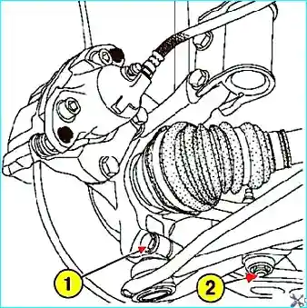
Fig. 1. Unscrewing the lower suspension arm mountings
Unscrew the suspension arm ball joint retaining bolt and the anti-roll bar link ball joint retaining nut (Fig. 1).
Press out the track rod end ball joint using the tool (Tav476).
Unscrew the upper bolt securing the connecting link between the subframe and the side member.
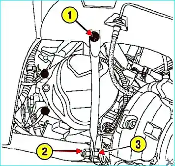
Fig. 2. Unscrewing the upper suspension arm mountings
Unscrew the lower nut of the subframe connecting link and the rear and front suspension arm retaining bolts (Fig. 2).
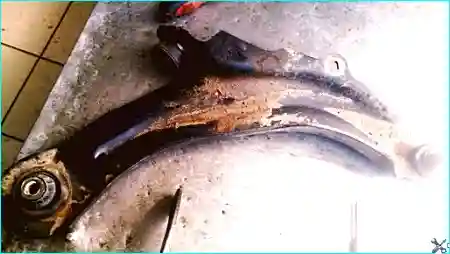
Fig. 3. Remove the suspension arm
Installing the suspension arm
Installation is carried out in the reverse order of removal.
The suspension arm retaining bolts must be replaced.
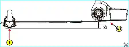
Fig. 4. Preventing bush preload when tightening the suspension arm during installation
During installation, to prevent preload on the bushes when tightening, position the suspension arm so that the centre distance X1 = 24 mm between the lower part of the arm ball joint and the lower part of the subframe, at the level of the centre hole W1 of the arm (Fig. 4).
Place a hydraulic jack under the subframe in the area of the suspension arm centre hole W1 and raise it until it contacts the subframe.
Lower the hydraulic jack by the dimension X1 = 24 mm.
Position the suspension arm ball joint cover on the hydraulic jack without changing the position of the arm.
In this position, tighten the front and rear suspension arm retaining bolts to the subframe to the specified torque of 105 N·m.
Remove the hydraulic jack.
Insert the suspension arm ball joint into the steering knuckle.
Install and tighten to the specified torque:
- the lower nut of the subframe connecting link (62 N·m);
- the upper bolt of the subframe connecting link (210 N·m);
- the anti-roll bar link ball joint retaining nuts (35 N·m);
- the suspension arm ball joint retaining nut (62 N·m);
- the front wheels and the front wheel retaining bolts (105 N·m).
Install the anti-roll bar link using the tool (Sus1413) and adapter (Sus1734).
Adjust the wheel alignment angles.