


The Renault Megane 2 instrument panel is a demountable construction consisting of a decorative panel and a reinforcement beam.
The decorative panel is made of plastic and is secured by screws to the reinforcement beam.
The control instruments and the vehicle controls, as well as the air conditioning and heating system controls, are mounted on the panel.
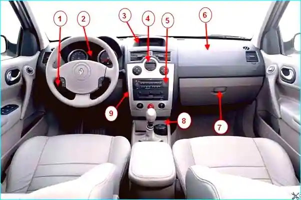
Fig. 1. Instrument panel: 1 — regulator block for the electric headlamp leveller and instrument cluster illumination; 2 — instrument cluster; 3 — information display; 4 — heating (air conditioning) and ventilation control panel; 5 — audio system head unit; 6 — passenger airbag; 7 — glove box; 8 — floor tunnel trim; 9 — instrument panel centre trim
The heating system air ducts are attached to the inside of the decorative panel.
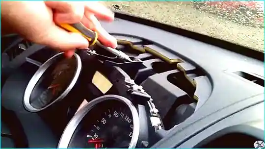
Fig. 2. The front passenger airbag is also installed in the instrument panel
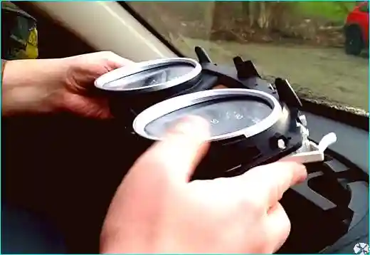
Fig. 3. The reinforcement beam is made of steel and serves as a mounting point for the steering column, wiring harnesses and electrical system components
Before carrying out any work on the safety system components, the airbag ECU must be locked using a diagnostic tool.
This locks all firing circuits and illuminates the airbag warning lamp continuously on the instrument panel (with the ignition on).
Locking the airbag ECU also unlocks the steering column electric lock.
It is strictly forbidden to work on pyrotechnic systems (airbags and seat belt pretensioners) near heat sources or open flames, as there is a risk of accidental deployment.
Removing the instrument panel decorative panel
Disconnect the negative battery terminal.
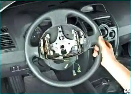
Fig. 4. Remove the steering wheel
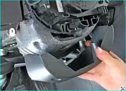
Fig. 5. Remove the steering column cover and the energy absorption element
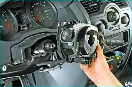
Fig. 6. Remove the steering column switches complete with holder and contact ring
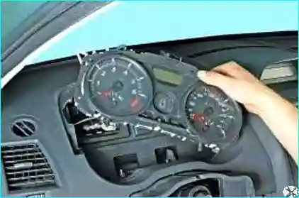
Fig. 7. Remove the instrument cluster – Instrument cluster replacement Renault Megane II
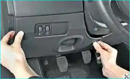
Fig. 8. Pull the upper part of the fusebox cover clips
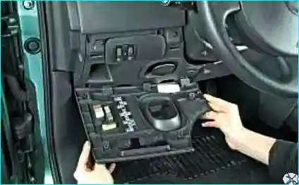
Fig. 9. Open the fusebox cover
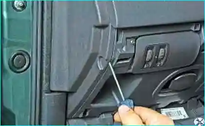
Fig. 10. Prise the left instrument panel trim with a screwdriver
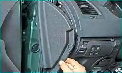
Fig. 11. Overcoming the resistance of the retaining clips, remove the left instrument panel trim
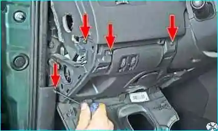
Fig. 12. Unscrew the four screws securing the lower left instrument panel trim, then move the trim aside as far as the wiring harness allows
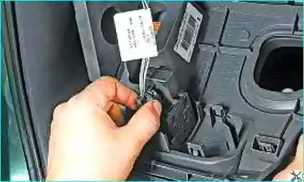
Fig. 13. Release the connector clip
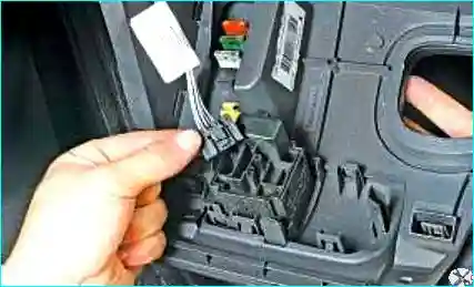
Fig. 14. Disconnect the wiring harness connector from the regulator block for the headlamp leveller and instrument cluster illumination
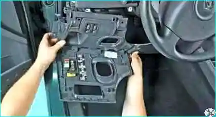
Fig. 15. Remove the lower left instrument panel trim complete with the regulator block and fusebox cover
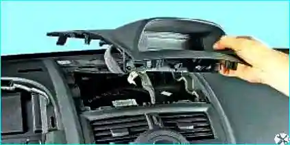
Fig. 16. Overcoming the resistance of the clips, move the display trim aside
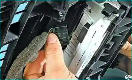
Fig. 17. Release the clips and disconnect the two wiring connectors from the information display
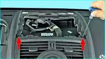
Fig. 18. Unscrew the two instrument panel retaining screws located under the display trim
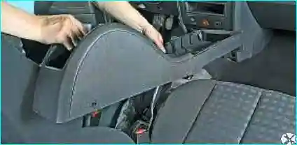
Fig. 19. Remove the floor tunnel trim – Replacing the centre console on a Renault Megane 2
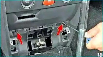
Fig. 20. Unscrew the two lower screws of the instrument panel centre trim
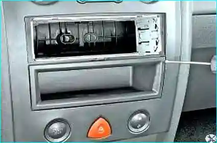
Fig. 21. Prise the cubby box housing with a screwdriver
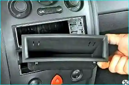
Fig. 22. Remove the cubby box housing
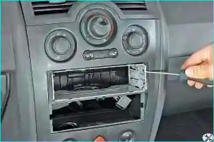
Fig. 23. Prise the audio system bracket and remove it
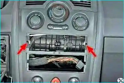
Fig. 24. Unscrew the two screws of the instrument panel centre trim
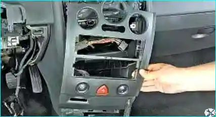
Fig. 25. Move the centre trim aside as far as the wiring harness allows
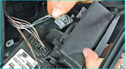
Fig. 26. Release the clips and disconnect the three wiring harness connectors from the switches
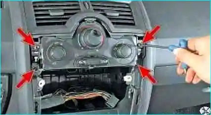
Fig. 27. Unscrew the four screws securing the centre vents of the heating and ventilation system
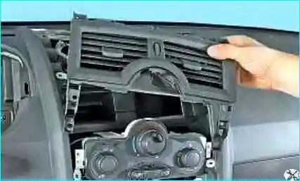
Fig. 28. Remove the centre vents
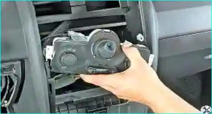
Fig. 29. Remove the heating and ventilation control unit
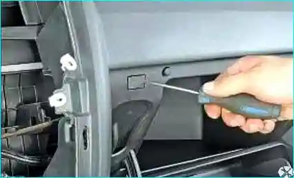
Fig. 30. Prise the blanking cover with a screwdriver
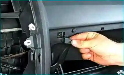
Fig. 31. Remove the screw cover of the glove box trim
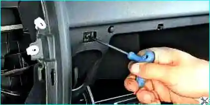
Fig. 32. Unscrew the glove box trim screw
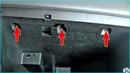
Fig. 33. Unscrew the three screws securing the glove box to the instrument panel reinforcement
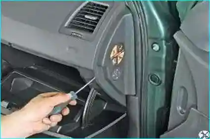
Fig. 34. Prise and move the right instrument panel trim aside as far as the wiring harnesses allow
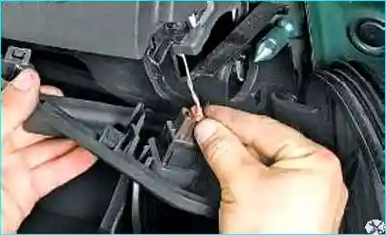
Fig. 35. Release the airbag connector clip
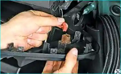
Fig. 36. Disconnect the wiring connector from the front passenger airbag switch
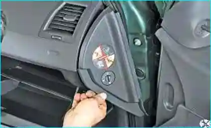
Fig. 37. Finally remove the right instrument panel trim
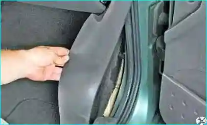
Fig. 38. Remove the right A-pillar trim. Also remove the left A-pillar trim
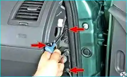
Fig. 39. Unscrew the three screws securing the instrument panel to the reinforcement on the right side
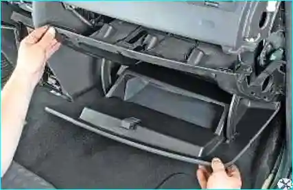
Fig. 40. Remove the glove box housing
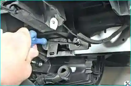
Fig. 41. Unscrew the instrument panel retaining screw on the passenger side
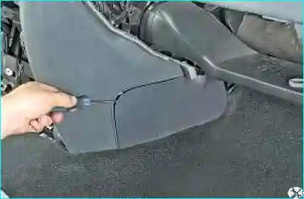
Fig. 42. Prise with a screwdriver
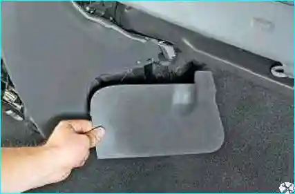
Fig. 43. Remove the instrument panel console covers
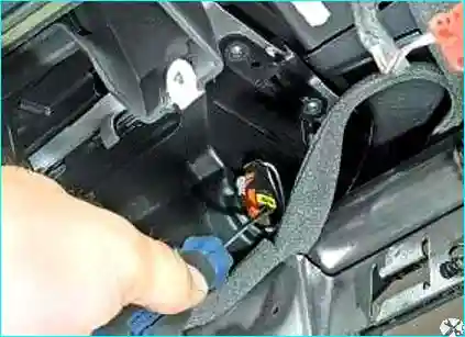
Fig. 44. Remove the clip
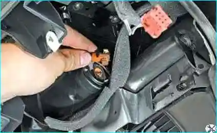
Fig. 45. Disconnect the wiring harness connector from the passenger airbag
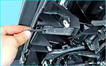
Fig. 46. Release the clip
Move the glove box lamp aside as far as its wiring harness allows.
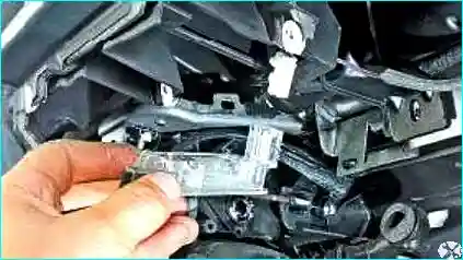
Fig. 47. Disconnect the connector and remove the glove box lamp
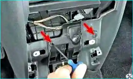
Fig. 48. Unscrew the two instrument panel retaining screws located under the centre trim
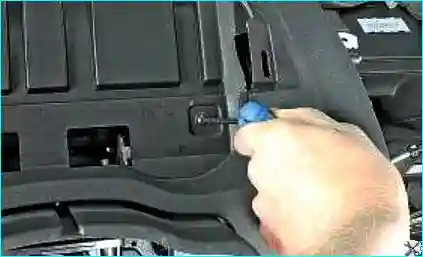
Fig. 49. Unscrew the instrument panel retaining screw located behind the instrument cluster
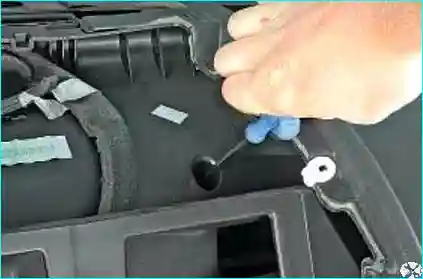
Fig. 50. Unscrew the instrument panel retaining screw located under the centre trim
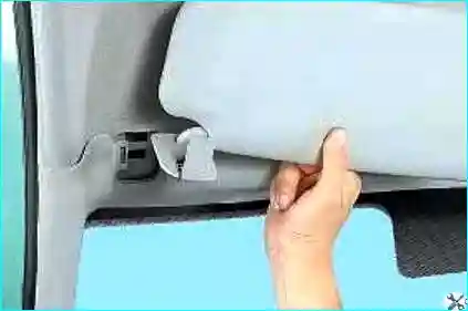
Fig. 51. Remove the sun visors

Fig. 52. Remove the A-pillar trims
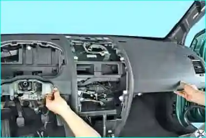
Fig. 53. Remove the decorative panel
Install the decorative panel in the reverse order.
Whenever the passenger airbag is removed, the nuts securing it to the instrument panel must be replaced.
Tighten the airbag module retaining screws to the specified torque of 2 N·m.
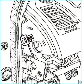
Fig. 54. Installing the stops
Install the two stops (Fig. 54).
Both stops must be replaced.
Before beginning installation, ensure that the wheels are still in the straight-ahead position and that the steering column switch block is aligned with the mark.
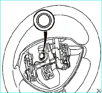
Fig. 55. Installing the steering wheel
The steering wheel should slide freely onto the splines (the splines have locating sections) (Fig. 55).
Be careful not to damage the splines on the locating sections.
The retaining bolt must be replaced after every steering wheel removal.
Tighten the steering wheel retaining bolt to the specified torque of 44 N·m.
Check the airbag ECU with the diagnostic tool.
Check that the airbag connectors are securely connected and locked.
Connect the earth lead of the passenger airbag module.
Tighten the retaining screw of the holder to the specified torque of 20 N·m.
Unlock the airbag ECU using the diagnostic tool.
Connect the cables to the battery terminals, starting with the positive terminal; carry out the necessary programming.
Tighten the battery cover retaining bolts to the specified torque of 4 N·m.
The remaining components are installed in the reverse order of removal.


