


Before beginning work to troubleshoot any electrical circuit, carefully study the corresponding wiring diagram to gain as clear an understanding as possible of its function.
The scope of fault finding is usually narrowed by progressively identifying and eliminating normally functioning elements within the same circuit.
When several components or circuits fail simultaneously, the most likely cause is a blown fuse or a poor earth connection (different circuits may in many cases be protected by a single fuse or share a common earth point).
Electrical failures are often due to simple causes such as corroded connector contacts, a faulty fuse, a blown fusible link, or a damaged relay.
Visually inspect the condition of all fuses, wiring and connectors in the circuit before proceeding with more detailed testing of its components.
If using diagnostic equipment for fault finding, carefully plan (with reference to the accompanying wiring diagrams) at which points in the circuit and in what sequence to connect the equipment for the most effective diagnosis.
Basic diagnostic equipment includes a circuit tester or voltmeter (a 12-volt test lamp with a set of connecting leads can also be used), a circuit continuity tester (probe) comprising a lamp, its own power source and a set of connecting leads.
In addition, you should always carry in the vehicle a set of jump leads (equipped with crocodile clips and preferably with a circuit breaker) for starting the engine from an external source (another vehicle's battery).
These can also be used for bridging and connecting various electrical components during circuit diagnosis.
As already mentioned, before checking a circuit with diagnostic equipment, determine the connection points using the wiring diagrams.
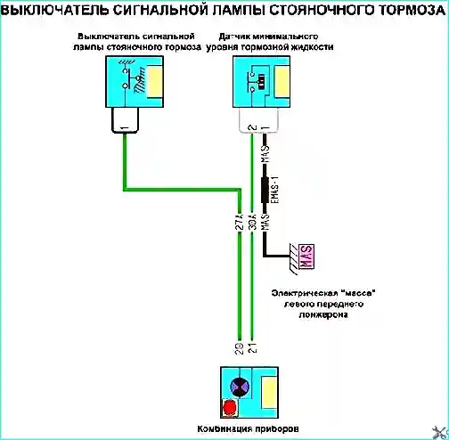
Fig. 1. Parking brake warning lamp switch
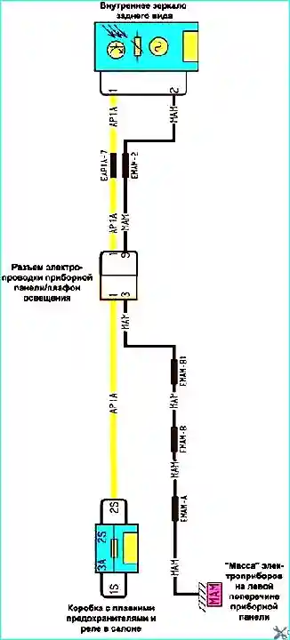
Fig. 2. Interior rear view mirror
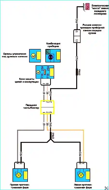
Fig. 3. Fog lamps
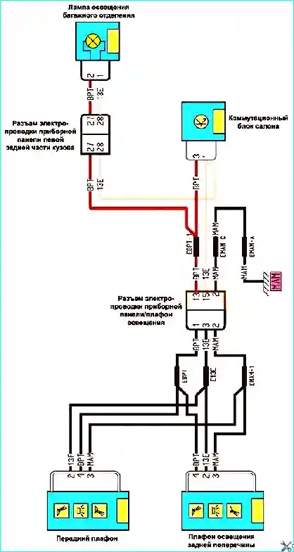
Fig. 4. Interior and luggage compartment lamps
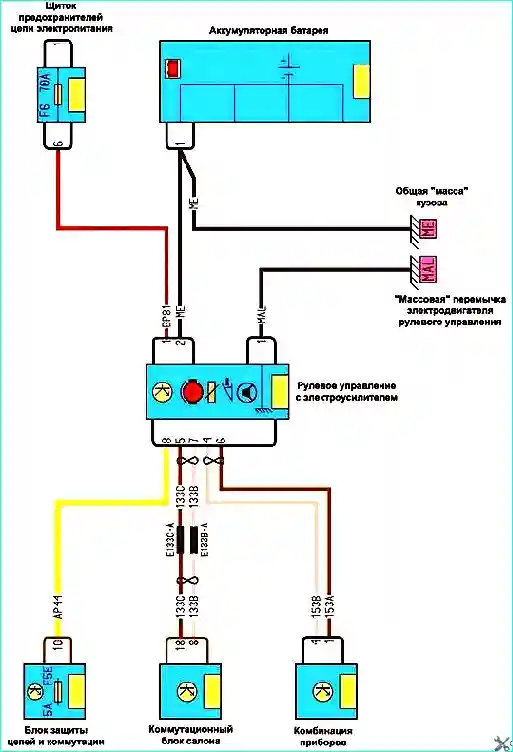
Fig. 5. Electric power steering
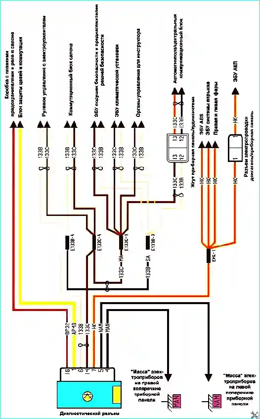
Fig. 6. Diagnostic connector
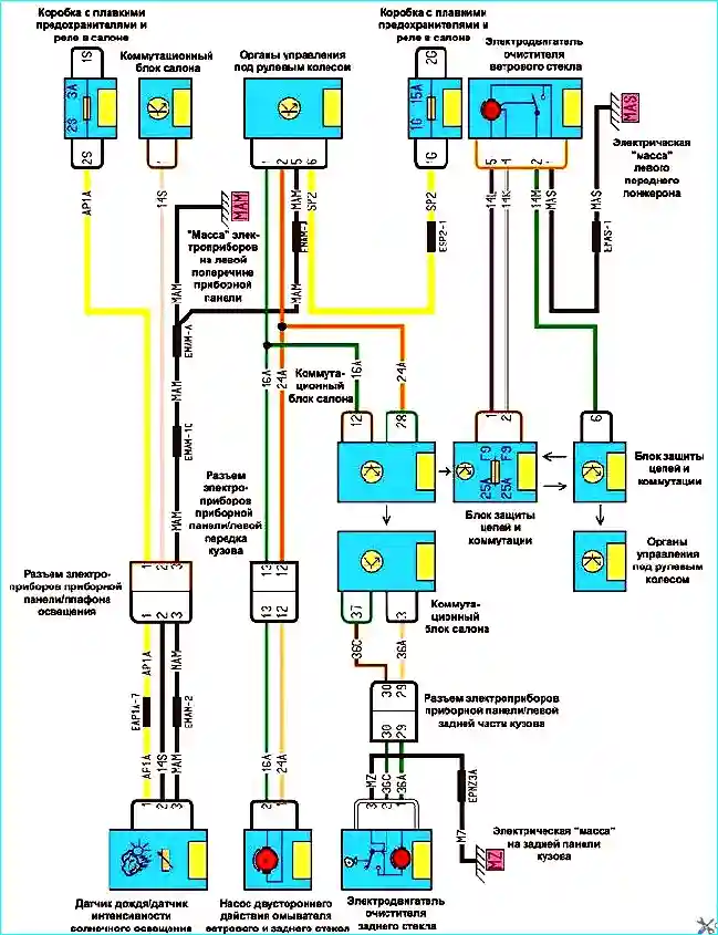
Fig. 7. Front and rear wipers and washers
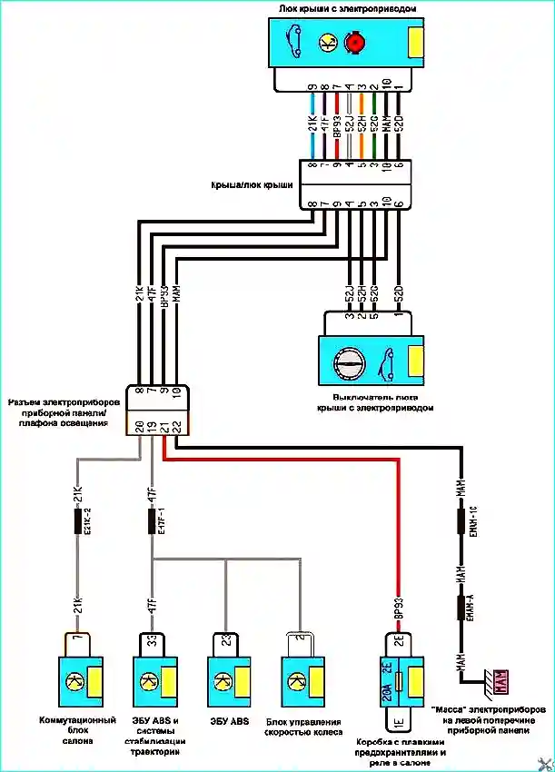
Fig. 8. Electric sunroof
All work on the vehicle's electrical system should be carried out with the battery disconnected.
The battery should only be connected or disconnected with the ignition switched off.
When checking electrical circuits, it is forbidden to short-circuit wires to earth or to test circuits by sparking, as this may damage electrical components.
It is forbidden to use fuses not specified by the vehicle manufacturer or rated for a higher current, or to use wire as a fuse replacement.
When replacing fuses, it is forbidden to use screwdrivers, as this may cause a short circuit in the electrical circuits.
It is forbidden to disconnect the battery with the engine running in order to avoid damaging the voltage regulator and the vehicle's electronic components.
When carrying out electric welding work on the vehicle, the cables must be disconnected from the battery terminals, the alternator and the control unit.
Regularly clean the battery terminals and cable ends to remove oxidation and dirt.
When charging the battery with a charger, disconnect the cables from the battery terminals.
A typical electrical circuit may include a main electrical component, various switches, relays, electric motors, fuses, fusible links or circuit breakers relating to that component, and the wiring and connectors serving to connect the main component to the battery and to the body earth.
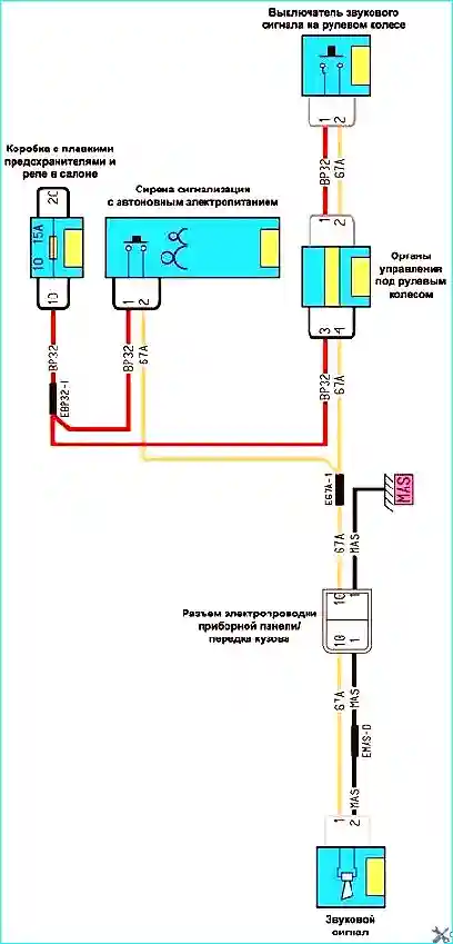
Fig. 9. Horn
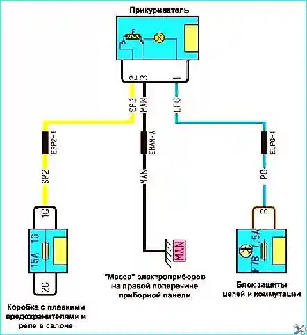
Fig. 10. Cigarette lighter
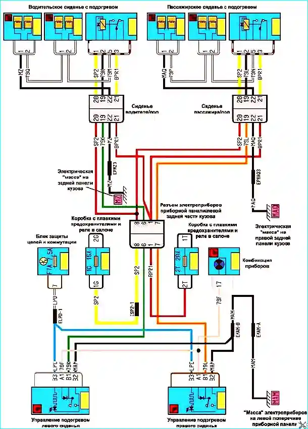
Fig. 11. Heated seats
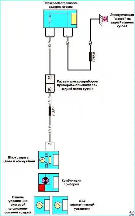
Fig. 12. Heated rear window
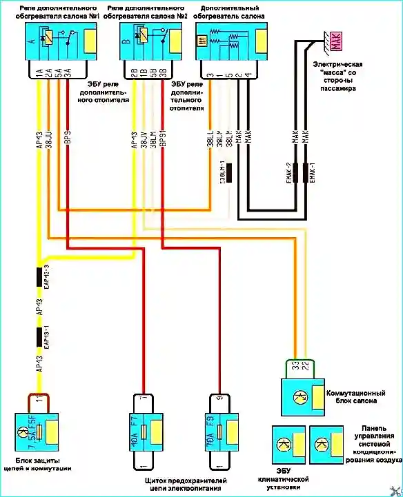
Fig. 13. Auxiliary heater in the cabin
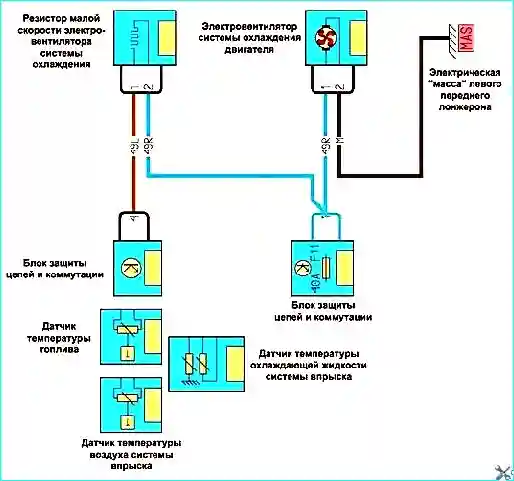
Fig. 14. Automatic climate control
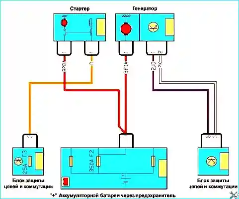
Fig. 15. Alternator and starter
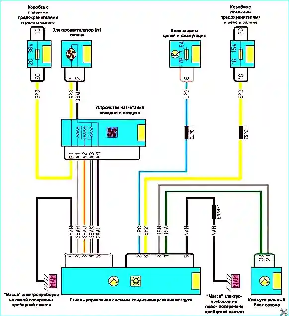
Fig. 16. Basic heating


