


In a fuel supply system without a fuel return branch to the tank, the fuel supply pressure is independent of engine load.
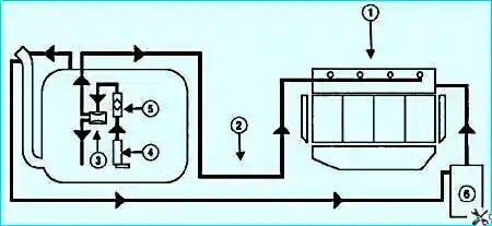
The fuel system includes components from the following subsystems:
- fuel supply, which includes the fuel tank, electric fuel pump with filter, fuel pressure regulator, pipelines, and fuel rail with injectors;
- air supply system, consisting of the air intake hose, air filter, throttle body, and idle speed control valve;
- fuel vapour recovery, which includes the charcoal canister, control valve, and connecting pipelines.
The functional purpose of the supply subsystem is to ensure the delivery of the required amount of fuel to the engine under all operating conditions.
The engines are equipped with an electronic engine management system with multi-point fuel injection.
In a multi-point injection system, the functions of mixture formation and metering the air-fuel mixture supply to the engine cylinders are separated.
Air is supplied by the air induction subsystem, which includes the throttle body, while the amount of fuel required at any given moment of engine operation is injected by the injectors into the intake manifold.
This control method makes it possible to ensure an optimal air-fuel mixture composition at each specific moment of engine operation, allowing maximum power to be achieved with the lowest possible fuel consumption and low exhaust emissions.
The fuel injection system (as well as the ignition system) is controlled by an electronic control unit, which continuously monitors engine load, vehicle speed, engine temperature, and the combustion process efficiency in the cylinders using appropriate sensors.
The fuel vapour recovery system prevents fuel vapours, which have a negative impact on the environment, from escaping from the fuel system into the atmosphere.
The system uses a method of vapour absorption by a charcoal canister.
Fuel vapours from the fuel tank are continuously drawn off through a pipeline and accumulate in the canister, which is filled with activated carbon (adsorbent).
During engine operation, the adsorbent is regenerated by purging the canister with fresh air, which enters the system under the action of vacuum transmitted through the pipeline from the intake manifold to the canister cavity when the valve opens.
The valve opening, and consequently the intensity of canister purging, depends on the throttle opening angle and is determined by the vacuum created in the intake manifold plenum of the running engine.
Fuel vapours from the canister are fed through a pipeline to the engine intake manifold and burned in the cylinders.
Malfunctions of the fuel vapour recovery system lead to unstable idling, engine stalling, increased exhaust emissions, and deterioration of vehicle drivability.
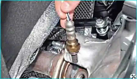
It is installed on the engine exhaust manifold and, together with the electronic control unit and injectors, forms a closed-loop control circuit for adjusting the air-fuel mixture composition supplied to the engine.
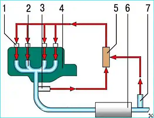
Based on the sensor signals, the engine control unit determines the amount of unburned oxygen in the exhaust gases and accordingly evaluates the optimality of the air-fuel mixture composition entering the engine cylinders at any given time.
Having detected a deviation of the mixture from the optimal 1:14 ratio (fuel to air, respectively), which ensures the most efficient operation of the catalytic converter, the control unit adjusts the mixture composition using the injectors.
As a result, the air-fuel mixture composition control loop is a closed-loop system.
The vehicle is equipped with two oxygen concentration sensors: the first one on the exhaust manifold, and the second one after the catalytic converter.
The first sensor is the control sensor (the ECU uses its signal to adjust fuel delivery), while the second is the diagnostic sensor (the ECU uses its signal to evaluate the catalytic converter efficiency).
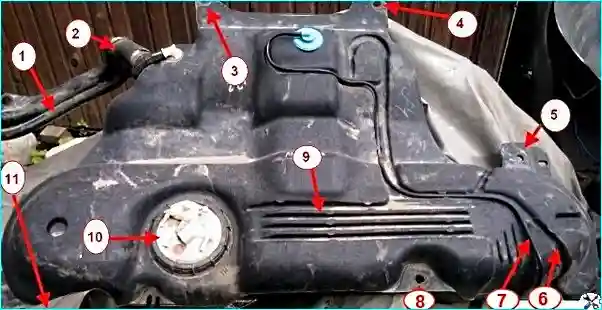
The fuel tank, moulded from petrol-resistant plastic, is installed under the vehicle floor in the rear section. To prevent fuel vapours from escaping into the atmosphere, the tank is connected to the charcoal canister by a pipeline.
An electric fuel pump is installed in the flange opening in the upper part of the tank.
From the pump, fuel passes through the pressure regulator to the fuel filter, mounted on the end of the fuel tank, and from there to the engine fuel rail, attached to the intake manifold.
From the fuel rail, fuel is injected by the injectors into the intake manifold.
The fuel system pipelines are tubes that connect the various components of the system.
The hoses of the fuel system are manufactured using a special technology from oil- and petrol-resistant materials.
The use of hoses of a different design can lead to fuel system failure and, in some cases, to fire.
Circular sealing rings are used in the connections of pipelines with fuel system components.
The use of seals of a different design is prohibited.
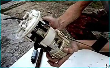
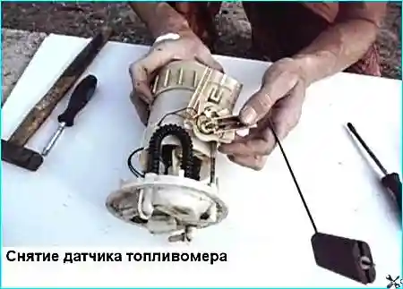
The fuel pump is of the submersible type, with an electric drive, and is of the rotary design.
The pump is of a non-serviceable design and cannot be repaired; if it fails, it must be replaced.
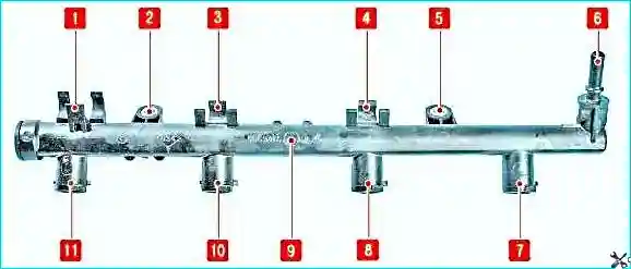
The injector rail 9 (Fig. 7) is a cast hollow part with connectors for installing the injectors and a connector 6 for connecting the high-pressure fuel line.
The injectors are sealed in their seats with rubber O-rings and secured with spring clips.
The assembled rail with injectors is inserted with the injector nozzles into the intake manifold openings and secured with two bolts.
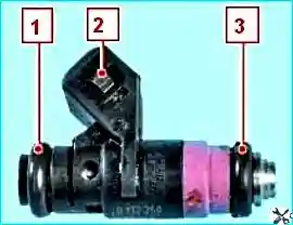
The injectors are attached to the rail, which supplies them with fuel, and their nozzles protrude into the intake manifold openings.
In the rail and intake manifold openings, the injectors are sealed with rubber O-rings 1 and 3 (Fig. 8).
The injector is designed for metered fuel injection into the engine cylinder and is a high-precision electromechanical valve.
Fuel under pressure flows from the rail through channels inside the injector body to the shut-off valve.
A spring presses the shut-off valve needle against the conical seat of the nozzle plate, holding the valve in the closed position.
The voltage applied from the engine control unit via the terminals 2 to the injector solenoid coil creates a magnetic field that pulls the armature with the shut-off valve needle inward.
The conical annular orifice in the nozzle plate opens, and fuel is injected through the nozzle body diffuser into the intake port of the cylinder head and then into the engine cylinder.
After the electrical pulse ceases, the spring returns the armature and shut-off valve needle to their initial position – the valve closes.
The amount of fuel injected by the injector depends on the duration of the electrical pulse.
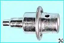
Excess fuel from the fuel rail is returned to the fuel tank through the return line via the fuel pressure regulator valve.
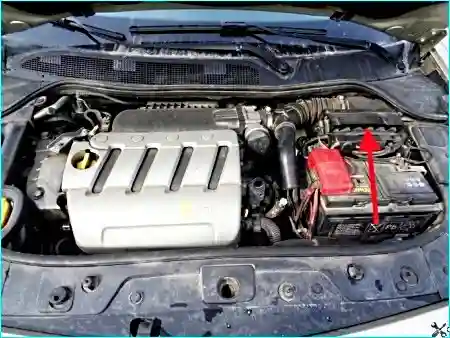
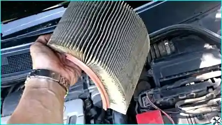
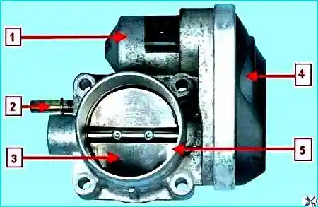
The throttle body (Fig. 12) is a simple regulating device used to control the amount of primary air supplied to the engine intake system.
It is mounted on the inlet flange of the intake manifold. A duct from the air cleaner housing is fitted onto the inlet duct of the throttle body.
The throttle body includes a stepper motor for throttle actuation.
There is no mechanical connection between the throttle body and the accelerator pedal.
The so-called "electronic throttle pedal" transmits information about the pedal position to the engine electronic control unit, which, in turn, taking into account vehicle speed, engaged gear, engine load, and crankshaft speed, opens the throttle plate to the required angle.
Fuel injection system related faults
The vehicles are equipped with a multi-point fuel injection system.
It is called multi-point because fuel is injected into each cylinder by a separate injector.
The fuel injection system allows reducing exhaust emissions while improving vehicle performance and fuel economy.
In the engine fuel injection system with feedback, the exhaust system is equipped with a catalytic converter and two oxygen concentration sensors, which provide the feedback.
The sensors monitor the oxygen content in the exhaust gases, and the electronic control unit uses their signals to maintain an air-fuel ratio that ensures the most efficient operation of the catalytic converter.
Before removing any components of the injection control system, disconnect the negative battery cable.
Disconnect the battery only when the ignition is switched off.
Do not start the engine if the battery cable terminals are loose.
Never disconnect the battery from the vehicle electrical system while the engine is running.
When charging, disconnect the battery from the vehicle electrical system.
Do not allow the electronic control unit (ECU) to exceed 65 °C in operation and 80 °C when not in operation (e.g., in a drying oven after painting).
If this temperature is exceeded, the ECU must be removed from the vehicle.
Do not disconnect or connect the wiring harness connectors from the ECU while the ignition is on.
Before performing electric arc welding on the vehicle, disconnect the battery cables and the wiring harness connectors from the ECU.
Perform all voltage measurements with a digital voltmeter having an internal resistance of at least 10 MΩ.
The electronic components used in the injection system are designed for very low voltage and can therefore be easily damaged by electrostatic discharge.
To prevent damage to the ECU from electrostatic discharge:
- do not touch the ECU connectors or electronic components on its circuit boards with your hands;
- when working with the programmable read-only memory (PROM) of the control unit, do not touch the IC pins.
When working in rainy weather, avoid getting water on the electronic components of the fuel injection system.
Carry out the injection system check in the following order:
Check the engine and battery ground connections.
Check the pressure regulator, fuel filter, and fuel pump.
Check the fuses and relays of the injection system components.
Check the reliability of the connector contacts with the wiring of the injection system components.
Check the injection system sensors.


