The engines fitted to Renault Mégane 2 vehicles are equipped with an electronic engine management system with multi-point fuel injection.
This system ensures compliance with modern emission and evaporation standards while maintaining high driving performance and low fuel consumption.
The controlling device in the system is the electronic control unit (ECU).
Based on information received from the sensors, the ECU calculates the parameters for fuel injection regulation and ignition timing control.
In addition, according to the programmed algorithm, the ECU controls the operation of the engine cooling fan motor and the electromagnetic clutch of the air conditioning compressor, performs self-diagnosis of system components, and alerts the driver to any faults detected.
In the event of failure of individual sensors or actuators, the ECU activates emergency modes that keep the engine operational.
The amount of fuel delivered by the injectors is determined by the duration of the electrical signal from the ECU.
The electronic unit monitors engine condition data, calculates fuel demand, and determines the required fuel injection duration (signal duration).
To increase the amount of fuel delivered, the signal duration is increased; to reduce fuel delivery, it is decreased.
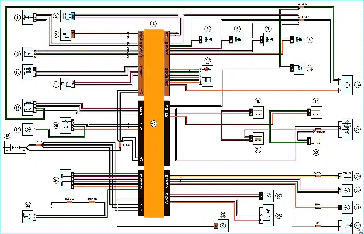
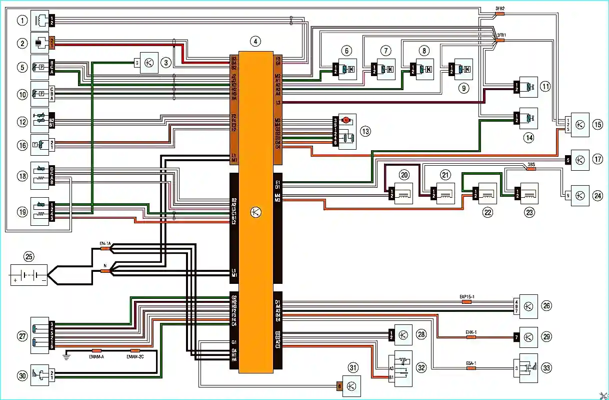
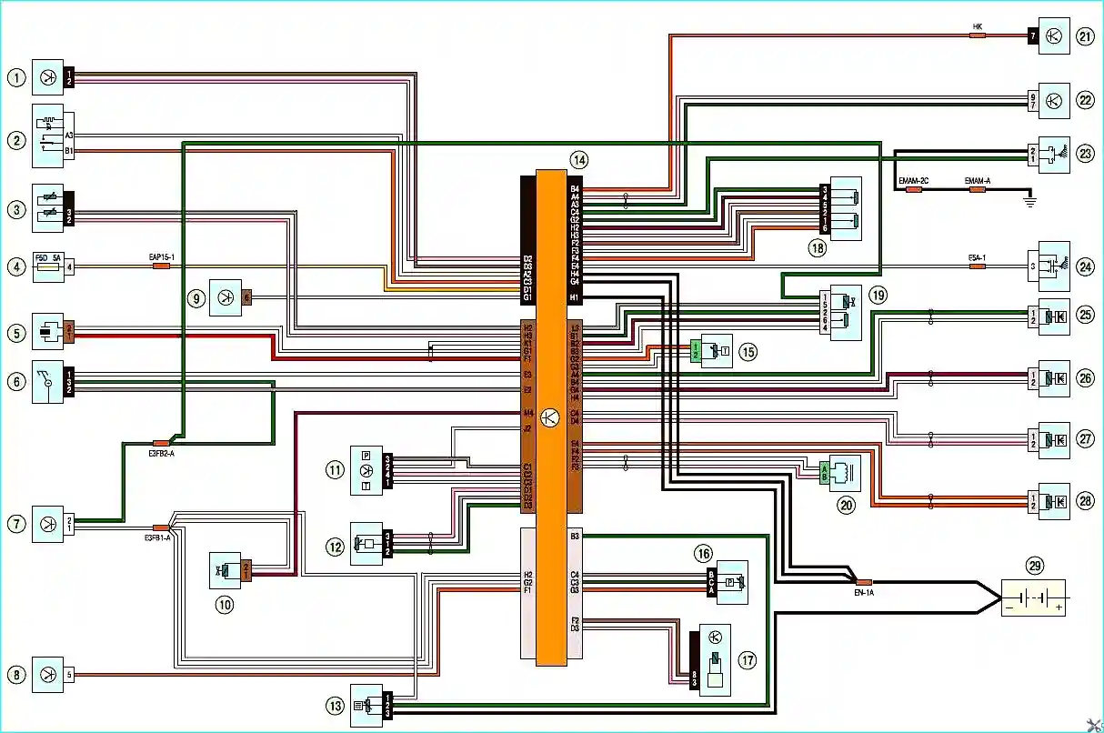
Shown below are the wiring diagrams of the engine management systems.
Fig. 1. Engine management system K4J and K4M: 1 — refrigerant pressure sensor; 2 — crankshaft position sensor; 3 — knock sensor; 4 — engine electronic control unit; 5, 6, 7, 8 — injector; 9 — manifold absolute pressure sensor; 10 — coolant temperature sensor; 11 — intake air temperature sensor; 12 — throttle body; 13 — charcoal canister of the fuel vapour recovery system; 14, 19, 26, 29, 30 — fuse box in the engine compartment; 15 — diagnostic oxygen concentration sensor; 16, 17, 21, 22 — ignition coil; 18 — battery; 20 — control oxygen concentration sensor; 23 — fuel module relay; 24 — throttle position sensor; 25 — clutch pedal position sensor; 27 — steering wheel switches; 28 — speed limiter switch; 31 — diagnostic connector; 32 — stop lamp switchFig. 2. Engine management system F4R: 1 — crankshaft position sensor; 2 — knock sensor; 3, 15, 17, 24, 26, 31 — fuse box in the engine compartment; 4 — engine electronic control unit; 5 — refrigerant pressure sensor; 6, 7, 8, 9 — injector; 10 — manifold absolute pressure sensor; 11 — camshaft with variable valve timing system; 12 — coolant temperature sensor; 13 — throttle body; 14 — charcoal canister of the fuel vapour recovery system; 16 — intake air temperature sensor; 18 — diagnostic oxygen concentration sensor; 19 — control oxygen concentration sensor; 20, 21, 22, 23 — ignition coil; 25 — battery; 27 — throttle position sensor; 28 — steering wheel switches; 29 — diagnostic connector; 30 — clutch pedal position sensor; 32 — speed limiter switch; 33 — stop lamp switchFig. 3. Engine management system K9K: 1 — steering wheel switches; 2 — speed limiter switch; 3 — coolant temperature sensor; 4, 7, 8, 9, 22 — fuse box in the engine compartment; 5 — knock sensor; 6 — camshaft position sensor; 10 — regulated fuel supply device; 11 — atmospheric pressure/air temperature sensor; 12 — fuel rail pressure sensor; 13 — water in fuel sensor; 14 — engine electronic control unit; 15 — fuel temperature sensor; 16 — refrigerant pressure sensor; 17 — pre-heating and post-heating unit; 18 — throttle position sensor; 19 — exhaust gas recirculation solenoid valve; 20 — crankshaft position sensor; 21 — diagnostic connector; 23 — clutch pedal position sensor; 24 — stop lamp switch; 25, 26, 27, 28 — injector; 29 — battery