


Place the vehicle on a two-post lift.
Disconnect the battery.
Remove the battery.
Remove the right-hand front wheel.
Remove the right-hand front wheel arch liner.
Remove the upper engine covers.
Install tools (Mot1453) and (Mot1453-01) with the retaining straps.
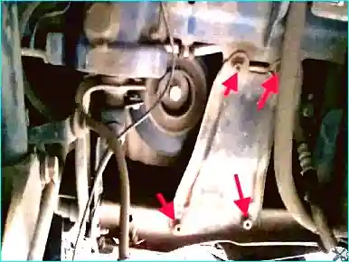
Fig. 1. Remove the right-hand side reinforcement of the radiator frame and the lower torque reaction rod
Disconnect the connectors, then disconnect the bonnet lock cable.
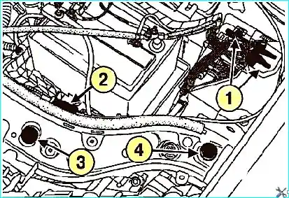
Fig. 2. Remove the retainer. Unscrew the fixing bolt and remove the front bumper
Disconnect the washer fluid pipes.
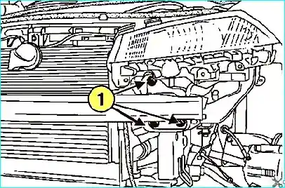
Fig. 3. Unscrew the front panel fixing bolts
Remove the front panel.
Remove the right-hand front drive shaft.
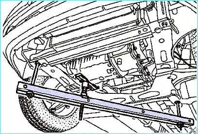
Fig. 4. Installing tool (Mot1672) with securing straps
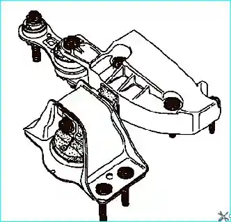
Fig. 5. Marking the pendulum support position
Mark the position of the pendulum support relative to the body (Fig. 5).
Remove the pendulum support.
Take care not to deform the air conditioning pipes.
Remove the auxiliary drive belt.
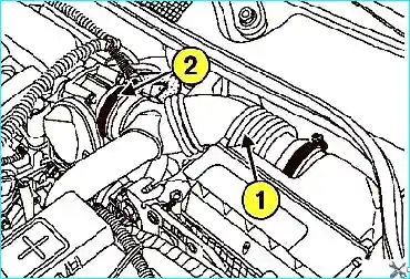
Fig. 6. Removing the air filter outlet duct and throttle body: 1 - air filter outlet duct, 2 - throttle body
Remove the air filter outlet duct, the throttle body, and the wiring connector from the lifting eye (Fig. 6).
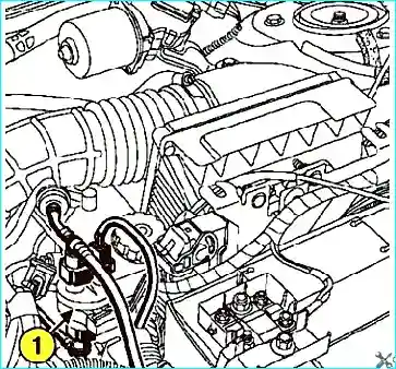
Fig. 7. Removing the canister purge solenoid valve: 1 - solenoid valve
Remove the canister purge solenoid valve (Fig. 7).
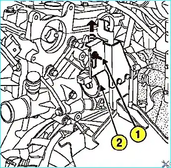
Fig. 8. Releasing the electric water pump: 1 - fixing nut, 2 - electric water pump
Unscrew the nut, pull the electric water pump bracket and move it aside (Fig. 8).
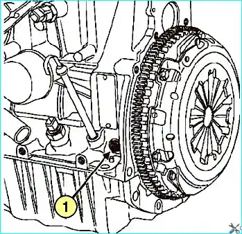
Fig. 9. Removing the TDC locking pin hole plug: 1 - plug
Unscrew the plug from the TDC locking pin hole (Fig. 9).
Remove the camshaft blanking plugs (Fig. 10).
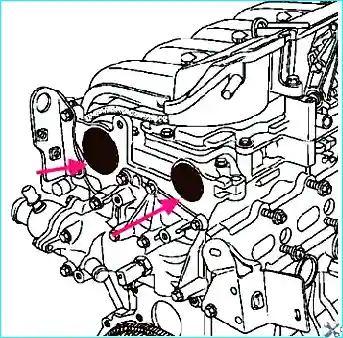
Fig. 10. Camshaft blanking plugs
When setting the valve timing, it is important to understand the engine design.
The crankshaft pulley may be keyed or without a key.
The camshaft pulleys are without a key.
The principle of this design is: first install and tension the belt, then tighten the pulleys.
The shafts themselves (crankshaft and camshafts) are locked in the TDC position.
The crankshaft is locked via a special hole using a pin – a bolt.
The camshafts are locked against rotation using a tool through the holes sealed by the plugs.
At the opposite ends of the camshafts there is an eccentric slot into which the tool is inserted.
The tool is installed when the camshaft slots are facing downwards relative to the centre.
Before belt tensioning, the camshaft pulleys are loose and can rotate on the shafts, while the shafts themselves are locked.
After the belt is installed and tensioned, the crankshaft and camshaft pulley fixing bolts are tightened.
First valve timing setting
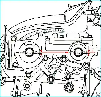
Fig. 11. Aligning the camshafts
Turn the engine clockwise (viewed from the timing belt side) so that the camshaft slots are facing downwards and almost horizontal, as shown in Figure 11.
Insert the TDC locking pin (Mot1054) between the balance hole and the crankshaft locking slot (Fig. 12).
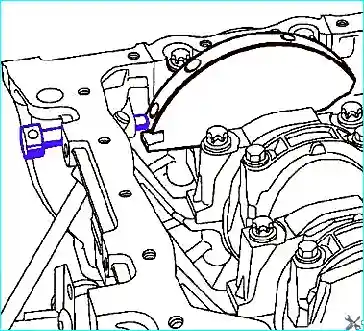
Fig. 12. Installing the TDC locking pin
Turn the crankshaft in the same direction until the TDC locking pin (Mot1054) engages in the crankshaft locking slot.
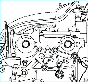
Fig. 13. Axial alignment of the camshaft slots
In the setting position, the camshaft slots are horizontal and offset downwards, as shown in Figure 13.
Remove the TDC locking pin.
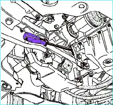
Fig. 14. Locking the flywheel
Remove the flywheel guard and the crankshaft pulley, locking the flywheel with a screwdriver (Fig. 14).
Install the TDC locking pin (Mot1054).
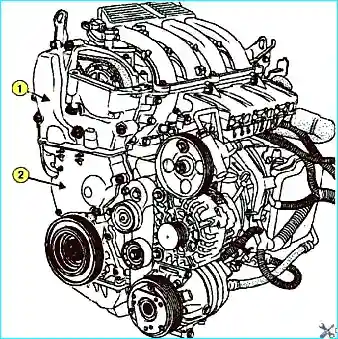
Fig. 15. Removing the timing belt covers: 1 - upper cover, 2 - lower cover
Remove the upper and lower timing belt covers (Fig. 15).
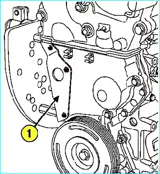
Fig. 16. Removing the heat shield: 1 - heat shield
Remove the heat shield (Fig. 16).
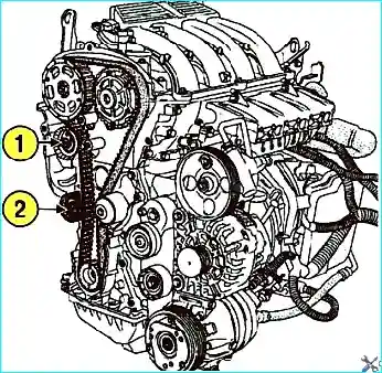
Fig. 17. Tensioner pulley fixing nut: 1 - nut, 2 - idler pulley
Release the timing belt tension by loosening the tensioner pulley fixing nut (Fig. 17).
Remove the idler pulley, the timing belt, and the crankshaft timing sprocket.
Never rotate the crankshaft in the opposite direction of rotation.
Second valve timing setting
Ensure that the phaser ring gear of the intake camshaft is securely locked (the ring gear cannot be turned left or right).
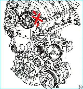
Fig. 18. Locking the phaser ring gear
Mount the gear (Mot1509-01) onto the special tool (Mot1509).
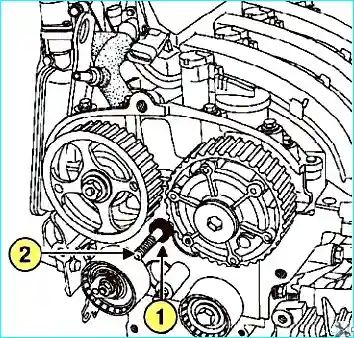
Fig. 19. Installing the distance sleeve: 1 - distance sleeve, 2 - stud
Fit the distance sleeve of the tool (Mot1509-01) onto the stud (Fig. 19).
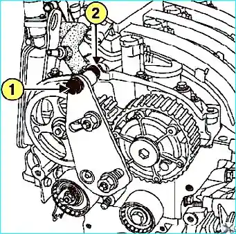
Fig. 20. Securing the upper bolt on the distance sleeve: 1 - upper bolt, 2 - distance sleeve
Fit the distance sleeve (Mot1509-01) between the tool and the cylinder head cover, tighten the upper bolt, and finally tighten the bolt and the shouldered nut.
Bring the gears of the tool (Mot1509) up to the camshaft timing sprockets.
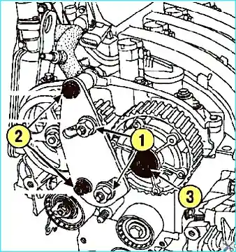
Fig. 21. Removing the intake phaser blanking plug: 1 - bolt and shouldered nut, 2 - timing sprocket fixing nuts, 3 - phaser blanking plug
Tighten the timing sprocket fixing nuts to 80 N·m.
Remove the intake phaser blanking plug (Fig. 21).
Unscrew the intake phaser fixing bolt.
Unscrew the exhaust camshaft timing sprocket fixing nut and the tool (Mot1509).
Remove the camshaft timing sprockets.
If necessary, unscrew the stud with its nut.
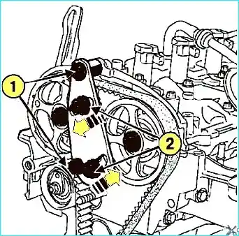
Fig. 22. Tightening the timing sprocket fixing studs: 1 - shouldered nut, 2 - timing sprocket fixing studs
Install the tool (Mot1509) with the gears (Mot1509-01).
Tighten the bolt and the shouldered nut.
Bring the tool gears into contact with the camshaft timing sprockets.
Tighten the timing sprocket fixing studs to 80 N·m (Fig. 22).
Unscrew the camshaft timing sprocket fixing nuts.
Remove the tool (Mot1509) and the camshaft timing sprockets.
Install the pre-degreased camshaft timing sprockets using the old nuts.
Using tool (Mot799-01), tighten the nuts to 15 N·m.
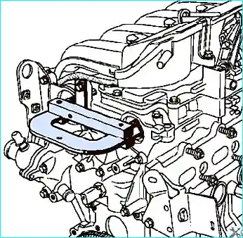
Fig. 23. Locking the camshaft ends
When replacing the timing belt, the crankshaft sprocket, idler and tensioner pulleys, and the timing and auxiliary drive belts must be replaced.
Using tool (Mot799-01), position the offset slots horizontally downwards, as shown above.
Secure the tool (Mot1496) to the camshaft ends (Fig. 23).
Unscrew the exhaust camshaft timing sprocket fixing nut and the intake phaser sprocket fixing bolt.
Unscrew the camshaft timing sprocket fixing nuts.
Ensure that the crankshaft is locked.
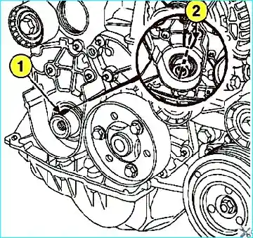
Fig. 24. Checking the crankshaft locking: 1 - crankshaft slot, 2 - ribs
The crankshaft slot must be positioned between the two ribs (Fig. 24).
Install the tensioner pulley with its projection in the groove (Fig. 25).
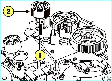
Fig. 25. Installing the tensioner pulley: 1 - projection, 2 - groove
Install the crankshaft timing sprocket, the timing belt, and the idler pulley.
Tighten the idler pulley fixing bolt to 50 N·m.
Checking belt tension
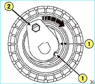
Fig. 26. Aligning the marks on the tensioner pulley: 1 - marks, 2 - key
Do not turn the tensioner pulley anti-clockwise.
Align the marks on the tensioner pulley using a 6 mm hex key (Fig. 26).
Tighten the tensioner pulley fixing nut to 7 N·m.
Install tools (Mot1509) with gears and (Mot1509-01) to lock the camshaft timing sprockets.
Tighten the bolt and the shouldered nut.
Screw the timing sprocket fixing nuts until they contact the camshaft sprockets.
Tighten to the specified torque:
- timing sprocket fixing stud nuts (80 N·m);
- old intake phaser fixing bolt (30 N·m);
- exhaust camshaft sprocket fixing nut (30 N·m).
Remove the tool (Mot1509) with (Mot1509-01).
Install the tool (Mot1509) to lock the camshaft timing sprockets.
Tighten the bolt and the shouldered nut.
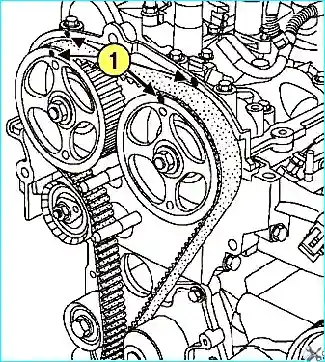
Fig. 27. Setting the camshaft timing sprockets relative to the bearing caps: 1 - alignment marks
Screw the timing sprocket fixing nuts until they contact the camshaft sprockets.
Tighten to the specified torque:
- timing sprocket fixing stud nuts (80 N·m);
- intake and exhaust camshaft timing sprocket fixing nuts (30 N·m).
Remove the tool (Mot1509) with (Mot1509-01).
Mark the position of the camshaft timing sprockets relative to the camshaft bearing caps with a pencil.
Align the TDC locking pin (Mot1054) and the camshaft locking tool (Mot1496).
Rotate the crankshaft by two turns clockwise (viewed from the timing belt side).
Installation
Install the lower and upper timing belt covers.
The crankshaft sprocket and its fixing bolt must be replaced.
Lock the flywheel using a large screwdriver.
Tighten the crankshaft sprocket fixing bolt to (40 N·m, then tighten a further 110°+10°).
To avoid damaging the crankshaft sprocket, do not start the engine without the auxiliary drive belt fitted.
Install the auxiliary drive belt.
Apply a small amount of sealant to the TDC locking pin hole plug and install it.
Install new intake and exhaust camshaft blanking plugs.
Install the remaining components in the reverse order of removal.


