

We examined the gearbox disassembly in the article — «Gearbox disassembly».
Materials used and precautions:
- To drive in the split rings and pins, use a copper or steel rod and a hammer; to drive out the pins — a drift punch and a hammer.
- To install small items (balls, pins), use a magnetised rod.
- Apply a thin layer of transmission oil or grease to the needle bearings and the guide rods of the lock mechanism.
- Apply sealant to the thread of the plugs and mounting bolts before screwing them in.
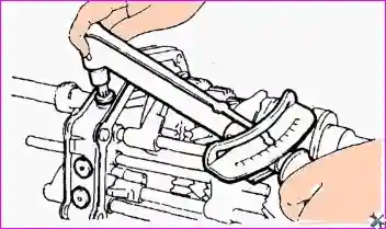
- Tighten the mounting bolts to the recommended torque; for multiple bolts, follow the diagonal sequence.
- When installing the snap rings, use pliers; the ring must fit tightly against the intermediate case.
- Do not fully tighten the shift block mounting bolt before completing the alignment of all elements.
Gearbox assembly
1. Assembly of the gearbox output shaft
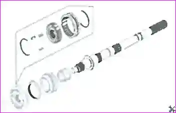
1) Assemble the third/fourth synchroniser components as shown in the figure. Install the third gear needle bearing, the third gear, the third/fourth/fifth synchroniser ring and the third/fourth synchroniser components.
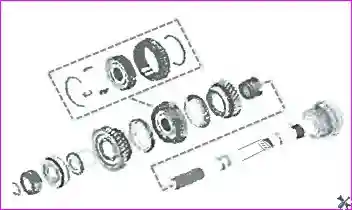
2) Assemble the first/second synchroniser components as shown in the figure. Install the second gear needle bearing, the second gear, the first/second synchroniser ring and the first/second synchroniser components. Apply a thin layer of transmission oil to the steel ball to install it on the input shaft. Then install the first gear, the first gear needle bearing, the first gear bushing, the bearing and the fifth gear. Install the fifth gear snap ring.
2. Installation of the output shaft into the intermediate case
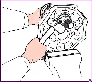
1) Install the output shaft into the intermediate case as shown in the figure.
2) Install the rear bearing snap ring of the output shaft using pliers.
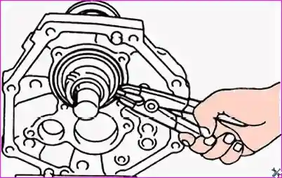
Note: the snap ring must fit tightly against the intermediate case.
3. Installation of the input shaft into the output shaft
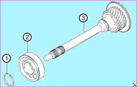
1) Install the input shaft bearing onto the input shaft and install the input shaft snap ring using pliers.
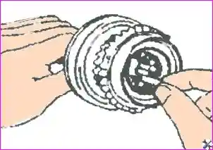
2) Apply grease to the needle bearing, install it into the input shaft and then install the third/fourth/fifth synchroniser ring.
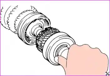
3) Screw the input shaft into the output shaft so that the three slots on the synchroniser ring align with the synchroniser key.
4. Installation of the intermediate shaft into the intermediate case
1) Install the snap ring on the rear bearing of the gearbox intermediate shaft.
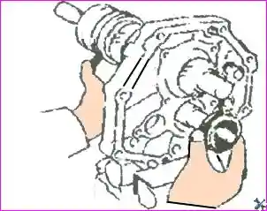
2) Install the gearbox intermediate shaft into the intermediate case, secure the intermediate shaft, and then install the intermediate shaft rear bearing.
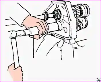
5. Installation of the rear bearing retaining plate
Install the rear bearing retaining plate and secure it with the mounting screws. Tighten the screws to the recommended torque.
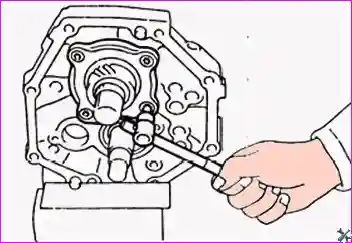
6. Installation of the intermediate gear and reverse shaft
1) Install the intermediate gear and the reverse shaft as shown in the figure.
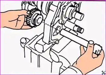
2) Install the retaining plate and secure it with the mounting bolts. Tighten the bolts to the recommended torque.
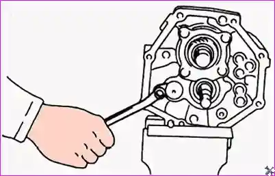
7. Installation of the rocker bracket
Install two small pins on the intermediate case, install the reverse rocker bracket and secure it with the mounting bolts. Tighten the bolts to the recommended torque.
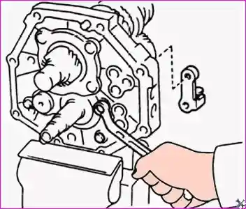
8. Installation of the detent ball and thrust washer
Install the detent ball and the fifth gear thrust washer.
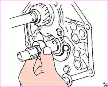
9. Installation of the intermediate shaft fifth gear
1) Assemble the intermediate shaft fifth gear as shown in the figure.
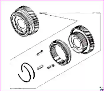
2) Apply transmission oil to the needle bearing.
3) Install the intermediate shaft fifth gear with the synchroniser sleeve and needle bearing.
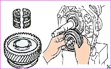
10. Installation of the synchroniser ring and fifth gear connecting gear
1) Install the synchroniser ring on the conical surface of the fifth gear connecting gear.
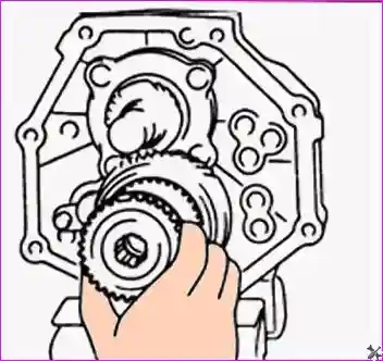
2) Remove the intermediate case from the vice.
3) Place the gearbox strictly vertically as shown in the figure. Install the fifth gear connecting gear and make sure the synchroniser ring slot is aligned with the synchroniser key.
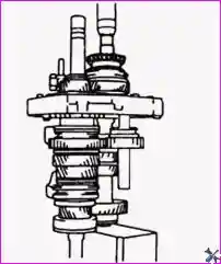
4) Select one split ring that will minimise the axial clearance.
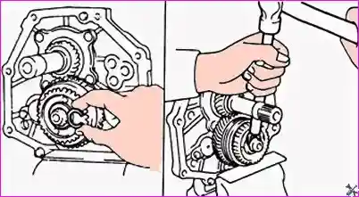
5) Install the split ring using a copper rod and a hammer.
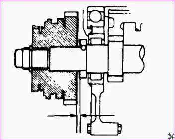
11. Measuring the fifth gear axial clearance
Measure the axial clearance of the intermediate shaft fifth gear using a feeler gauge.
Standard value: 0.1–0.3 mm. Maximum value: 0.3 mm.
12. Installation of the third/fourth and first/second fork shafts and forks
1) Install the first/second shift fork and the third/fourth shift fork.
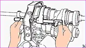
2) Install the third/fourth shift fork shaft into the intermediate case.
3) Screw in and tighten to the recommended torque the third/fourth shift fork mounting bolts.
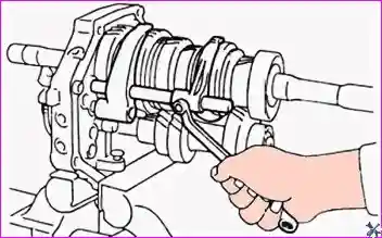
13. Installation of the first/second shift fork shaft
1) Apply grease to the lock mechanism guide rod and install it on the first/second shift fork shaft.
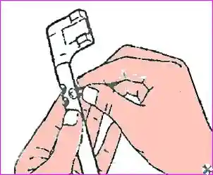
2) Install the short lock mechanism pin into the intermediate case using a magnetised rod.
3) Install the first/second shift fork shaft into the first/second shift fork and the intermediate case.
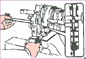
4) Screw in and tighten to the recommended torque the first/second shift fork mounting bolt.
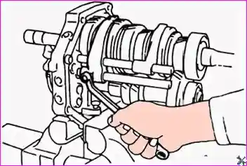
14. Installation of the reverse shaft, lever and block
1) Install the reverse block, the reverse lever and two E-clips on the reverse rocker.
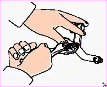
2) Install the rocker on the reverse rocker bracket.
3) Apply grease to the lock mechanism guide rod and install it on the reverse fork shaft.
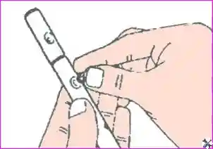
4) Install the lock mechanism pin into the intermediate case using a magnetised rod.
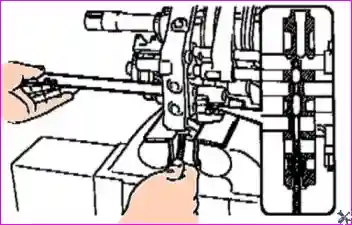
5) Install the reverse fork shaft into the reverse lever and the intermediate case.
15. Installation of the fifth/reverse guide block, fork and shaft
1) Install the fifth/reverse guide block on the reverse fork shaft.
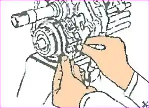
2) Install the fifth gear fork.
3) Install the detent ball into the fifth/reverse guide block using a magnetised rod.
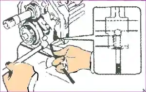
4) Install the fifth gear fork shaft.
5) Install the lock mechanism steel ball into the intermediate case using a magnetised rod.
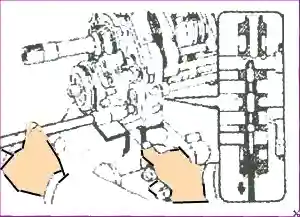
6) Install the fifth gear fork shaft into the intermediate case.
7) Drive the elastic cylindrical pin into the fifth gear fork using a drift punch and a hammer.
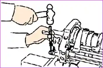
8) Install the fifth/reverse fork shaft into the fifth/reverse guide block.
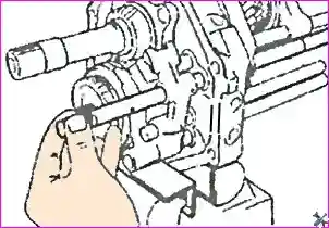
9) Drive the elastic cylindrical pin into the fifth/reverse guide block using a drift punch and a hammer.
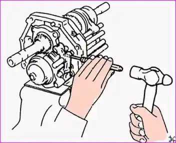
16. Installation of the shift fork shaft split washers
Install the shift fork shaft split washers using a steel rod and a hammer.
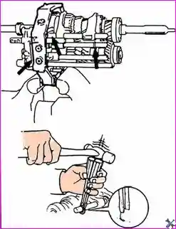
17. Installation of the balls, springs and threaded plugs
1) Install the balls and springs.
Note: install the short spring into the lower part of the intermediate case.
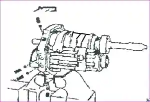
2) Apply sealant to the thread of the threaded plugs.
3) Screw in and tighten to the recommended torque the threaded plugs.
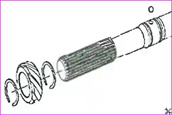
18. Installation of the speedometer drive gear
Install the speedometer drive gear.
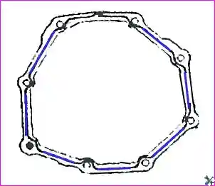
19. Installation of the gearbox case
1) Apply sealant to the gearbox case as shown in the figure.
2) Place the intermediate case strictly vertically as shown in the figure.
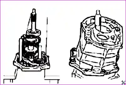
3) Install the gearbox case onto the intermediate case as shown in the figure.
20. Installation of the front bearing snap ring and front cover
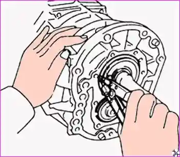
1) Install two snap rings on the input shaft bearing and the front intermediate shaft bearing using pliers.
2) Install the front cover.
Note: first apply sealant to the front cover mounting surface.
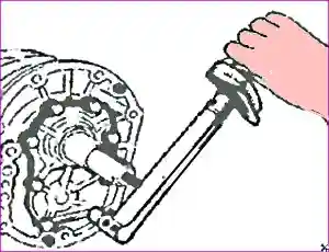
3) Apply sealant to the thread of the mounting bolts.
4) Screw in and tighten to the recommended torque the mounting bolts.
21. Installation of the rear case, shift shaft and shift block
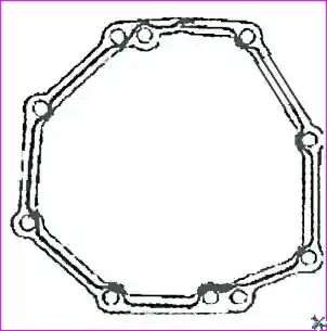
1) Install the components such as the limit mechanism and oil pipe on the gearbox rear case.
2) Apply a bead of sealant to the gearbox rear case as shown in the figure.
3) Install the shift shaft assembly with the shift lever into the gearbox rear case and then engage third gear.
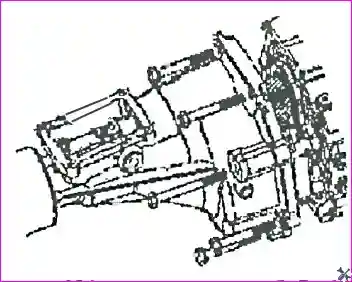
4) Place the shift block through the upper opening of the rear case so that the shift shaft can move through the shift block.
Note: do not fully tighten the mounting bolt at this stage.
5) Insert the shift lever into the slot of the third/fourth fork shaft and then align the fifth/reverse fork shaft with the rear case mounting hole to install it into the gearbox rear case.
6) Screw in and tighten to the recommended torque the gearbox rear case mounting bolts.
7) Screw in and tighten to the recommended torque the shift block mounting bolts.
22. Installation of the steel balls, springs and threaded plugs
1) Apply sealant to the thread of the threaded plugs.
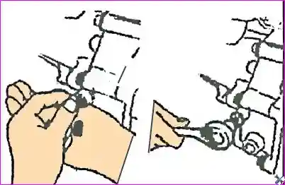
2) Install the steel balls, springs and threaded plugs. Tighten the threaded plugs to the recommended torque.
23. Checking shaft rotation
Make sure the input and output shafts rotate properly.
24. Installation of the positioning mechanism components
Install the positioning mechanism components.
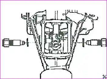
25. Installation of the reverse light switch
Install the reverse light switch.
26. Installation of the gearbox cover with shift mechanism
1) Apply a bead of sealant to the mounting surface of the gearbox cover with shift mechanism.
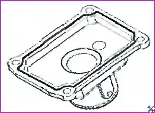
2) Screw in and tighten to the recommended torque the mounting bolts.
27. Installation of the speedometer driven gear
1) Install the speedometer driven gear.
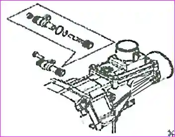
2) Screw in and tighten to the recommended torque the mounting bolt.
28. Installation of the gearbox case
1) Install the gearbox case.
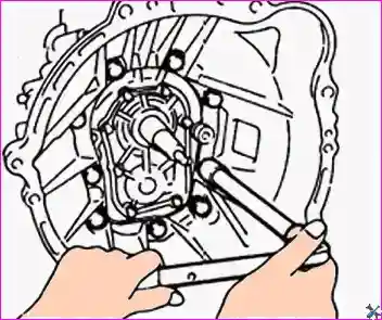
2) Screw in and tighten to the recommended torque the mounting bolts.
29. Installation of the drain and breather plugs, clip and clutch elements
Screw in the drain plug and the breather plug. Install the wiring clip, the earth wire, the clutch release bearing and the clutch release fork.
30. Checking gearbox operation
Check the gearbox operation.


