

The gearbox is disassembled for inspection and replacement of worn parts.
Materials used and precautions:
- To remove covers and cases, use a plastic mallet — apply light blows, avoiding deformation of the seating surfaces.
- To extract small items (steel balls, pins), use a magnetised rod.
- Apply a thin layer of clean transmission oil to the needle bearings and conical surfaces of the gears.
- Apply sealant to the plug threads before screwing them in.
- Tighten the mounting bolts to the recommended torque; for multiple bolts, follow the diagonal sequence.
- Select the snap rings so that the axial clearance is less than 0.1 mm.
- Drain the oil from the gearbox into a suitable container; dispose of the used oil in accordance with environmental requirements.
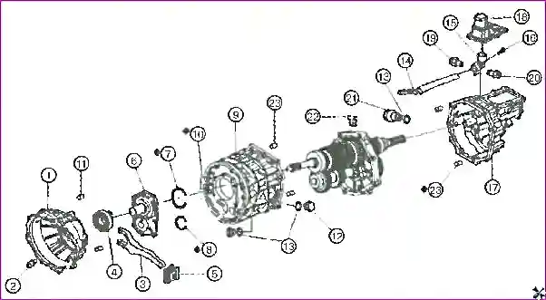
Gearbox disassembly
1. Oil drain
Loosen the hex plug and remove the washer, then drain the oil from the gearbox.
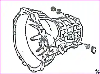
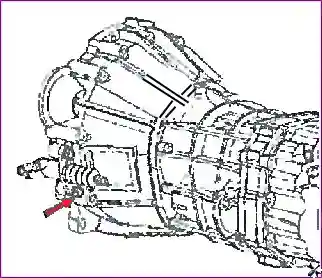
2. Removal of the clutch slave cylinder
Loosen the mounting bolts and remove the clutch slave cylinder.
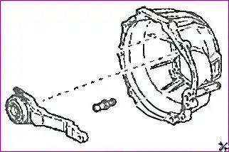
3. Removal of the boot, release fork and bearing
Remove the boot, the clutch release fork and the release bearing.
4. Removal of the reverse light switch
Remove the reverse light switch.

5. Removal of the release fork support
Remove the release fork support.
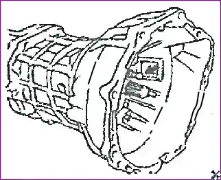
6–7. Removal of the clutch housing
Loosen the clutch housing mounting bolts.

Apply a few light blows to the clutch housing with the plastic mallet and remove it.

8. Removal of the shift lever cover
Loosen the six bolts securing the shift lever cover to the rear gearbox case, then remove the shift lever cover.
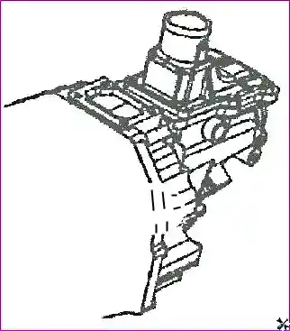
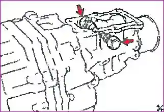
9. Removal of the positioning mechanisms
Remove the components of the left and right positioning mechanisms.
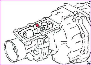
10. Loosening the bolt
Loosen the bolt.
11. Removal of the rear gearbox case
Loosen the bolt securing the rear case to the gearbox case, apply a few light blows to the rear case with the plastic mallet and remove the rear gearbox case.
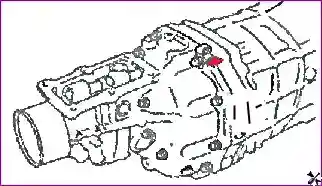
12. Removal of the front cover
- Loosen the bolts securing the front cover to the gearbox case.
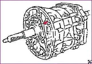
- Apply a few light blows to the front cover with the plastic mallet and remove the front gearbox cover.
13. Removal of the bearing snap rings
Remove the input shaft bearing snap ring and the front intermediate shaft bearing snap ring.

14. Removal of the gearbox case
Apply a few light blows to the gearbox case with the plastic mallet and remove it.

Removal of the shift components
1–3. Removal of the spring and steel ball
Secure the intermediate plate in a vice. Loosen the spring threaded plug. Remove the spring and the steel ball using a magnetised rod.
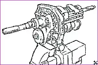
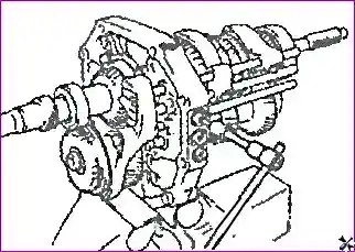
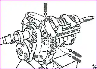
4–8. Removal of the first/second shift forks and shafts
Loosen the bolts securing the first gear shift fork and the second gear shift fork.

Remove the snap rings of the first gear shift fork shaft and the second gear shift fork shaft.

Remove the second gear shift fork shaft and the second gear shift fork.
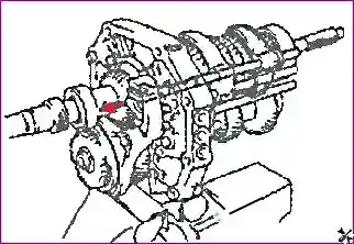
Remove the shift lock pin and the shift lock guide rod using a magnetised rod.

Remove the first gear shift fork shaft and the first gear shift fork.
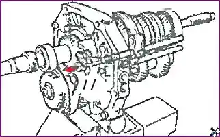
9–11. Removal of the third gear shift fork and shaft
Remove the third gear shift fork snap ring.

Remove the elastic cylindrical pin.
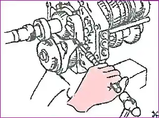
Remove the third gear shift fork shaft and the third gear shift fork.

12–15. Removal of the lock mechanism and rocker bracket
Extract the short shift lock pin and the steel ball using a magnetised rod.

Extract the steel ball and spring from the reverse rocker.

Remove the reverse rocker.
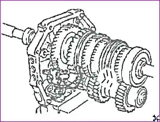
Loosen the bolts of the reverse rocker bracket and remove the bracket.
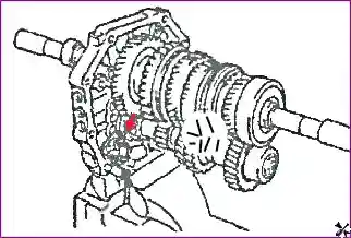
16–18. Removal of the speedometer gear
Remove the speedometer shaft snap ring.

Remove the speedometer drive gear and the steel ball.
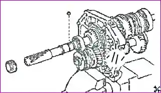
Remove the speedometer shaft snap ring.
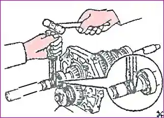
19–24. Removal of the rear bearing and fifth gear components
Remove the output shaft rear bearing snap ring.

Remove the output shaft rear bearing.
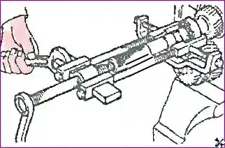
Remove the bushing.
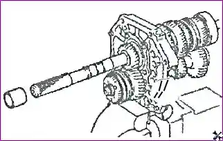
Remove the fifth gear intermediate shaft.

Remove the fifth gear synchroniser ring, the fifth gear intermediate shaft components and the needle bearing.
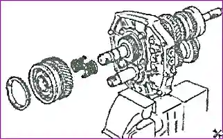
Remove the thrust washer and pin of the fifth gear.
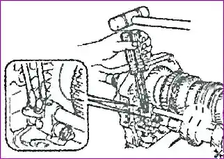
25–31. Removal of the baffle, intermediate gear and shafts
Loosen the bolts of the output shaft bearing baffle and remove the bearing baffle.

Extract the reverse intermediate gear shaft and the reverse intermediate gear.
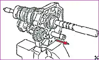
Remove the intermediate shaft rear bearing.

Remove the intermediate shaft.

Remove the input shaft assembly.
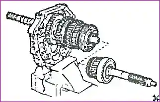
Remove the output shaft bearing snap ring.
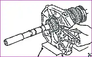
Apply a few blows to the intermediate plate and extract the output shaft assembly.
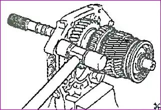
Input shaft disassembly and assembly
Input shaft disassembly
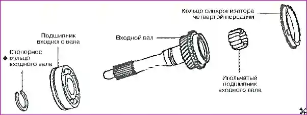
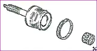
1. Remove the fourth gear synchroniser ring and the input shaft needle bearing.
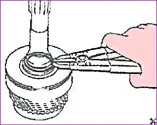
2. Remove the input shaft snap ring.
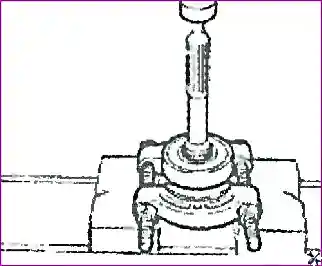
3. Remove the input shaft bearing.
Input shaft assembly
1. Install the input shaft bearing.

2. Select the input shaft snap ring.
Note: select the input shaft snap ring so that the axial clearance is less than 0.1 mm.
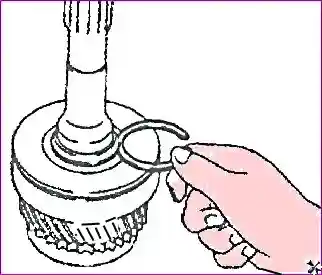
3. Install the input shaft snap ring.
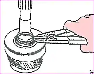
4. Install the fourth gear synchroniser ring.
- Apply a thin layer of clean transmission oil to the conical surface of the fourth gear and then install the fourth gear synchroniser ring.
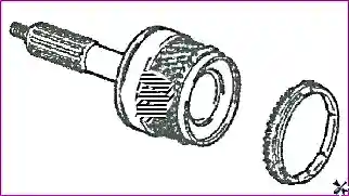
- Check the axial clearance between the fourth gear synchroniser ring and the fourth gear.
Standard value: 1.2 ± 0.5 mm.
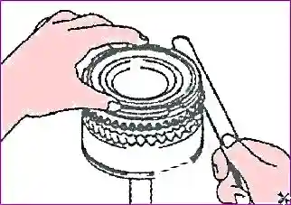
5. Try to turn and press the synchroniser ring to check its operation.
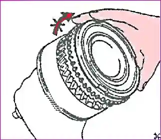
6. Install the input shaft needle bearing.
- Apply a thin layer of clean transmission oil to the inner surface of the input shaft.
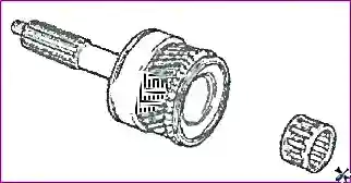
- Install the input shaft needle bearing.
Output shaft disassembly
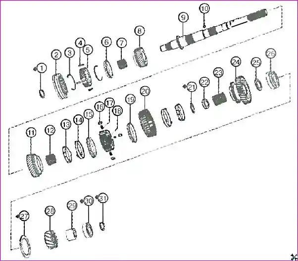
1–8. Output shaft disassembly
1. Remove the fifth gear, the output shaft bearing, the first gear thrust washer and the first gear from the output shaft.

2. Remove the first gear synchroniser ring, the first gear needle bearing and the first gear needle bearing bushing.
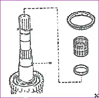
3. Remove the first gear synchroniser hub snap ring using two screwdrivers.
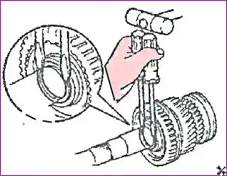
4. Remove the first/second synchroniser, the second gear synchroniser ring, the second gear and the second gear needle bearing.
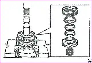
5. Disassemble the first/second synchroniser.
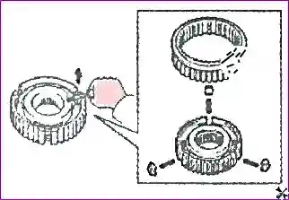
6. Remove the second gear synchroniser hub snap ring.
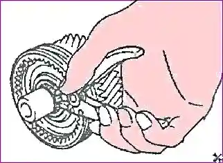
7. Remove the third/fourth synchroniser, the third gear synchroniser ring, the third gear and the third gear needle bearing.
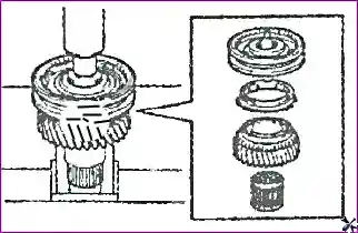
8. Disassemble the third/fourth synchroniser.

Output shaft component inspection
1–4. Clearance checks
1. Measure the clearance between the synchroniser ring and the gear using a feeler gauge.
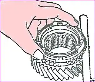
Clearance values:
- First gear: 1.2 ± 0.55 mm
- Second gear: 1.2 ± 0.55 mm
- Third gear: 1.2 ± 0.45 mm
2. Try to turn and press the synchroniser ring to check its operation.

3. Check the clearance between the first gear shift fork and the first gear synchroniser sleeve.
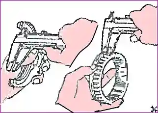
- Measure the slot size of the first gear shift fork using a calliper. Standard value: 5.28 mm.
- Measure the protrusion size of the first gear synchroniser sleeve using a calliper. Standard value: 5.00 mm.
- Calculate the clearance between the first gear shift fork and the first gear synchroniser sleeve. Standard value: 0.28 mm.
4. Check the clearance between the second gear shift fork and the second gear synchroniser sleeve.
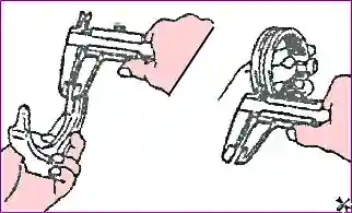
- Measure the protrusion size of the second gear shift fork using a calliper. Standard value: 10.00 mm.
- Measure the slot size of the second gear synchroniser sleeve using a calliper. Standard value: 10.2 mm.
- Calculate the clearance between the second gear shift fork and the second gear synchroniser sleeve. Standard value: 0.20 mm.
5. Output shaft technical condition check
1. Measure the outer diameter of each output shaft gear using a micrometer.

| Gear | Value, mm |
|---|---|
| A | 38.000 |
| B | 47.000 |
| C | 38.987 |
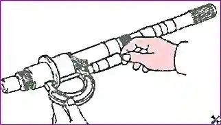
2. Measure the output shaft flange width using a micrometer. Standard value: 5.0 mm.
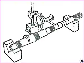
3. Measure the output shaft radial runout using a dial indicator.
Standard value: less than 0.015 mm.
4. Measure the inner diameter of each output shaft gear using a bore gauge.
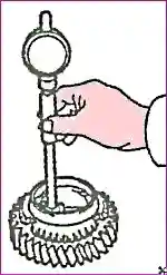
| Gear | Value, mm |
|---|---|
| First gear | 46.0275 |
| Second gear | 53.0275 |
| Third gear | 44.0275 |
Output shaft assembly
1–6. Assembling the synchronisers and installing the third gear
1. Assemble the first/second synchroniser.
- First install the three springs and then press the springs into the synchroniser keys using a screwdriver or another suitable tool.

- Install the first gear synchroniser sleeve.
Note: the first/second synchroniser has identification marks on surfaces "a" and "b".

2. Assemble the third/fourth synchroniser. To do this, install the synchroniser hub, the synchroniser key and the expander ring on the synchroniser sleeve.
Note: the third/fourth synchroniser has identification marks on surfaces "a" and "b".
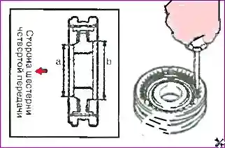
3. Install the third gear and the third/fourth synchroniser on the output shaft.
- Apply a thin layer of clean transmission oil to the shaft and the third gear needle bearing.
- Place the synchroniser ring on the third gear and align the synchroniser ring slot hole with the synchroniser key.

- Install the needle bearing into the third gear.
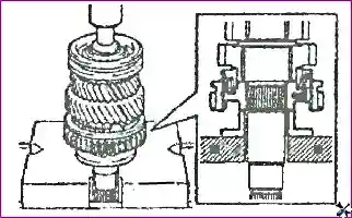
4. Press the third/fourth synchroniser onto the output shaft.
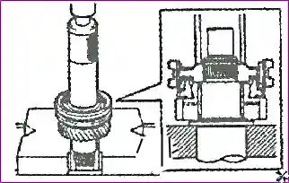
5. Select the output shaft snap ring.
Note: select the output shaft snap ring so that the axial clearance is less than 0.1 mm.
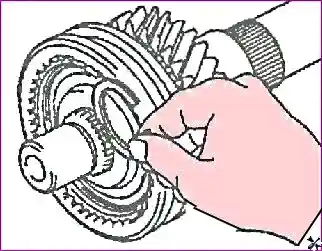
6. Install the output shaft snap ring.
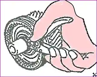
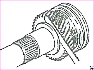
7. Measure the third gear axial clearance using a feeler gauge.
Standard value: 0.175 mm.
8–12. Installing the second and first gears
8. Install the first gear and the first/second synchroniser.
- Apply a thin layer of clean transmission oil to the shaft and the second gear needle bearing.
- Place the second gear synchroniser ring on the second gear and align the three intermediate ring protrusions with the three gear slots.
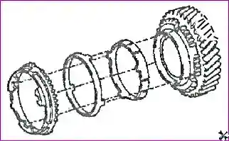
- Install the second gear needle bearing and the second gear.
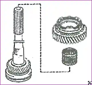
- Install the first/second synchroniser.
Note: be careful not to mix up the installation direction of the first/second synchroniser.
9. Select the output shaft snap ring.
Note: select the output shaft snap ring so that the axial clearance is less than 0.1 mm.
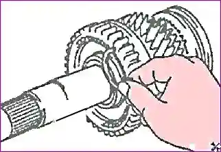
10. Install the output shaft snap ring using a screwdriver.
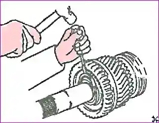
11. Measure the second gear axial clearance using a feeler gauge.
Standard value: 0.175 mm.
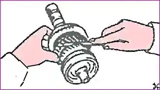
12. Install the first gear. To do this, install the first gear needle bearing bushing, the first gear needle bearing, the first gear synchroniser ring and the first gear in the order shown in the figure.
Note: apply a thin layer of clean transmission oil to the output shaft, the needle bearing and the conical surface of the first gear before aligning the three intermediate ring protrusions of the first gear synchroniser with the gear slots.

13–17. Installing the thrust washer, bearing and fifth gear
13. Install the first gear thrust washer. To do this, install the pin and the thrust washer on the output shaft.
Note: make sure the pin is installed correctly.
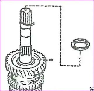
14. Install the output shaft bearing.
The side of the output shaft bearing with the snap ring groove must face rearwards.
Lift the first gear thrust washer with a screwdriver or another suitable tool while pressing on the output shaft bearing to prevent it from falling out.

15. Measure the first gear axial clearance using a feeler gauge. Standard value: 0.325 mm.
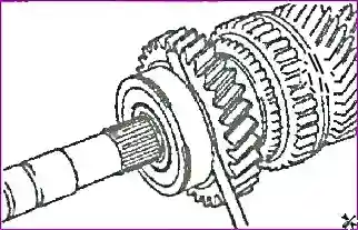
16. Install the fifth gear on the output shaft.
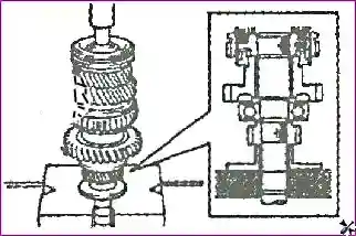
17. Measure the radial clearance of the output shaft gears using a dial indicator.

| Gear | Value, mm |
|---|---|
| First gear | 0.265 |
| Second gear | 0.265 |
| Third gear | 0.265 |
Intermediate shaft
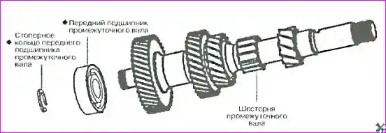
Intermediate shaft disassembly
1. Remove the front intermediate shaft bearing snap ring.

2. Remove the front intermediate shaft bearing.

Intermediate shaft assembly
1. Measure the diameters of the rear bearing and the fifth gear of the intermediate shaft.
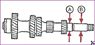
| Measurement point | Value, mm |
|---|---|
| A | 34.00 |
| B | 30.00 |
2. Install the front intermediate shaft bearing. Note: make sure the bearing side with the groove faces downwards.
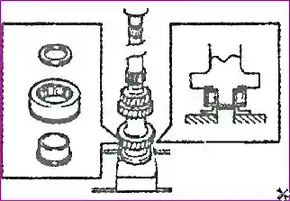
3. Select the intermediate shaft snap ring.
Note: select the intermediate shaft snap ring so that the axial clearance is less than 0.1 mm.
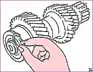
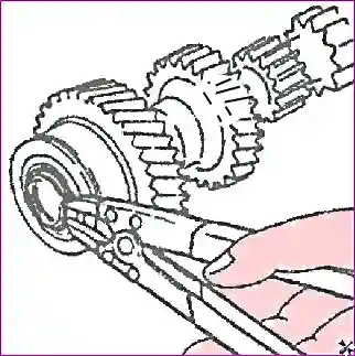
4. Install the intermediate shaft snap ring.
Front cover
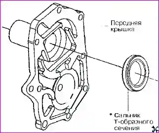
Front cover disassembly
Remove the T-section oil seal from the front cover.
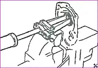
Front cover assembly
Install the T-section oil seal of the front cover.
Note: apply a thin layer of clean transmission oil to the outer surface of the T-section oil seal lip.
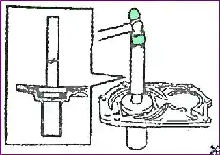
Rear gearbox case

Rear gearbox case disassembly
1. Remove the shift shaft and shift block from the rear gearbox case.
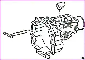
2. Remove the rear gearbox case boot using a special tool.
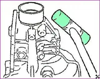
3. Loosen the threaded plug using a special tool.
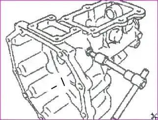
4. Remove the elastic cylindrical pin and extract the reverse gear lock mechanism using a special tool.

5. Loosen the threaded plug using a special tool.
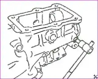
6. Loosen the hex head bolt with washer and remove the lubrication guide.
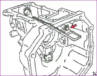
7. Remove the rear gearbox case oil seal using a special tool.

Rear gearbox case assembly
1. Install the lubrication guide and secure it with the hex head bolt with washer, then install the lubrication guide nozzle.
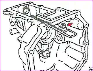
2. Screw in the threaded plug using a special tool.
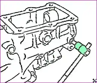
3. Install the reverse gear lock mechanism.
- Install the reverse gear lock mechanism into the bore.
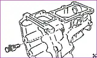
- Install the elastic cylindrical pin.

4. Screw in the threaded plug using a special tool.
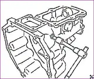
5. Install the rear gearbox case oil seal.
Note: the clearance between the installed oil seal surface and the rear gearbox case surface must be 0 ± 0.05 mm.

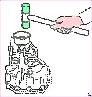
6. Install the rear gearbox case boot using a special tool.
Intermediate plate
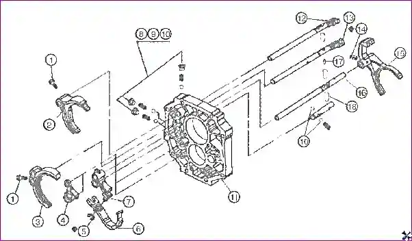
Intermediate plate disassembly
Note: the intermediate plate disassembly operations are described at the beginning of the article «Removal of the shift components».
Intermediate plate assembly
1. Secure the intermediate plate in a vice.
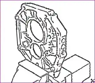
2. Install the output shaft onto the intermediate plate.
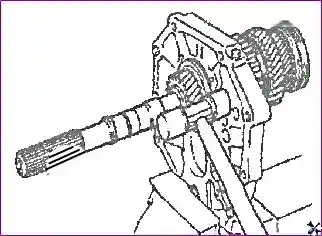
3. Install the output shaft snap ring.
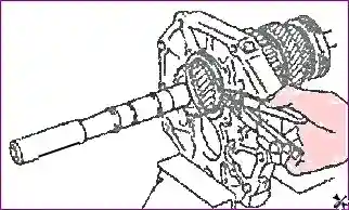
4. Install the bushing onto the output shaft.

5. Install the output shaft rear bearing.
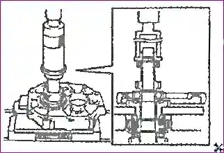
6. Select the output shaft snap ring.
Note: select the output shaft snap ring so that the axial clearance is less than 0.1 mm.
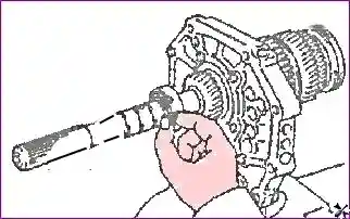
7. Install the output shaft snap ring using a screwdriver.

8. Install the input shaft.
- Install the input shaft onto the output shaft while turning the input shaft.
- Make sure the synchroniser ring slot is aligned with the synchroniser key.
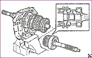
9. Install the intermediate shaft into the gearbox intermediate plate.
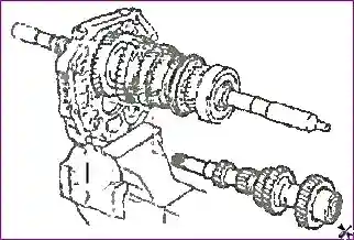
10. Install the intermediate shaft rear bearing.
Note: the snap ring is built into the intermediate shaft rear bearing.

11. Install the reverse intermediate gear and the reverse intermediate gear shaft onto the gearbox intermediate plate.
Note: the side with the groove of the reverse intermediate gear must face rearwards.

12. Install the output shaft rear bearing baffle and secure it with the mounting bolts. Tighten the bolts to the recommended torque using a torque wrench. Tightening torque: 12.6–23.4 N·m.
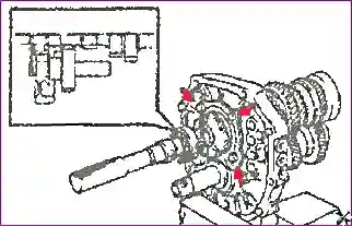
13. Install the fifth gear thrust washer.
- Install the pin into the intermediate shaft pin bore.
- Install the fifth gear thrust washer.
Note: be careful not to mix up the installation direction of the thrust washer.

14. Install the intermediate shaft fifth gear.
- Install the third gear synchroniser sleeve.
- Install the third gear synchroniser key, the synchroniser expander ring, the synchroniser spring and the intermediate shaft snap ring.

- Install the intermediate shaft fifth gear needle bearing, the intermediate shaft fifth gear and the fifth gear synchroniser gear ring.
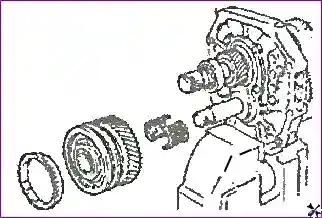
15. Engage the fifth gear.
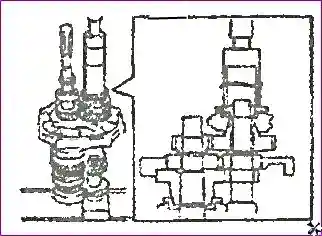
16. Measure the fifth gear axial clearance using a feeler gauge. Standard value: 0.225 mm.

17. Select the intermediate shaft snap ring.
Note: select the intermediate shaft snap ring so that the axial clearance is less than 0.1 mm.

18. Install the intermediate shaft snap ring using a screwdriver.
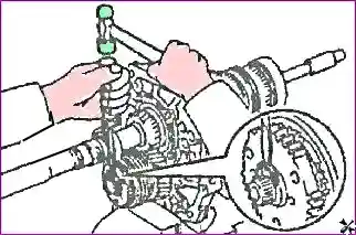
19. Install the reverse rocker bracket and secure it with the mounting bolts. Tighten the bolts to the recommended torque using a torque wrench. Tightening torque: 12.6–23.4 N·m.

20. Connect the reverse rocker to the reverse shift fork. Install the E-clip using a screwdriver to secure the reverse rocker and the reverse shift fork.
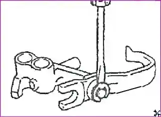
21. Install the reverse rocker and reverse shift fork assembly into their mounting position.
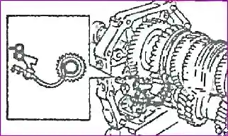
22. Install the steel ball and spring into the reverse rocker.
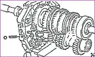
23. Install the reverse shift fork shaft.
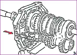
24. Install the steel ball and the shift lock guide rod.
- Install the steel ball into the reverse rocker.
- Install the shift lock guide rod into the gearbox intermediate plate and install the steel ball into the reverse shift fork shaft.
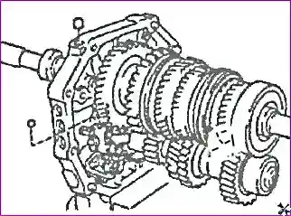
25. Install the third gear shift fork and the third gear shift fork shaft.
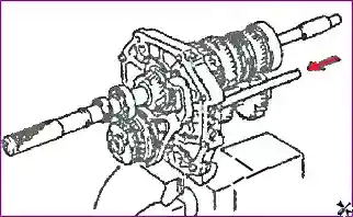
26. Install the reverse shift fork shaft snap ring and the third gear shift fork shaft snap ring using a screwdriver.
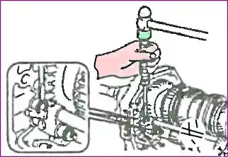
27. Install the shift lock guide rod into the gearbox intermediate plate.

28. Install the first gear shift fork and the first gear shift fork shaft.
- Apply a thin layer of clean transmission oil inside the pin bore of the first gear shift fork shaft and install the short shift lock pin inside the shift fork shaft.
- Then insert the first gear shift fork shaft into the first gear shift fork through the gearbox intermediate plate.
Note: be careful not to mix up the installation direction of the first gear shift fork. Be careful not to drop the short shift lock pin.
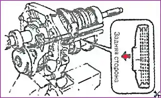
29. Install the shift lock guide rod into the gearbox intermediate plate.
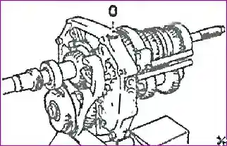
30. Install the second gear shift fork and the second gear shift fork shaft.
Note: the second gear shift fork shaft must be installed through the gearbox intermediate plate bore, the first gear shift fork bore and the second gear shift fork bore. Be careful not to mix up the installation direction of the second gear shift fork.

31. Secure the third gear shift fork and the third gear shift fork shaft with the elastic cylindrical pin, installing it using a special tool.
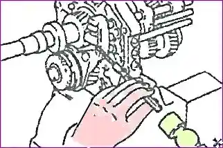
32. Install the first gear shift fork shaft snap ring and the second gear shift fork shaft snap ring using a screwdriver.
33. Secure the first gear shift fork and the second gear shift fork with the mounting bolts. Tighten the bolts to the recommended torque using a torque wrench. Tightening torque: 15.6–23.4 N·m.
34. Install the steel balls, springs and screw in the threaded plugs.
- Install the steel balls and springs.

- Screw in the threaded plugs and tighten them to the recommended torque using a torque wrench. Tightening torque: 12.95–24.05 N·m.
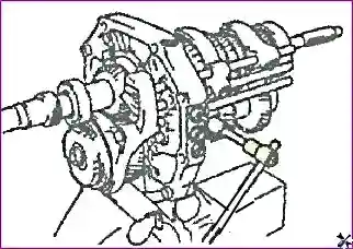
35. Install the speedometer shaft snap ring.
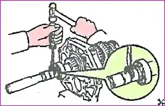
36. Install the steel ball and the speedometer drive gear.

37. Install the speedometer shaft snap ring.
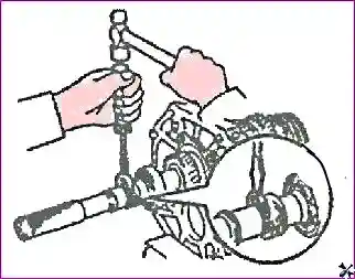

38. Place the magnet in its mounting position.


