
Synchronization of the impulse wheels of the crankshaft and the drive gear shaft of the injection pump
The need to install (reinstall) the impulse wheels of the crankshaft and the shaft of the injection pump drive gearbox for their synchronization may be caused by the rearrangement of the injection pump drive gearbox during the current diesel engine repair
The installation of impulse wheels according to the proposed scheme is carried out to synchronize the signals of the crankshaft speed sensors and the input shaft of the high-pressure fuel pump drive and is provided by linking the sensor signals to a common starting point of the shaft position at the moment the piston of the first cylinder of the top dead center (TDC) passes.
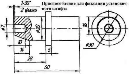
In order to ensure the correct installation of the impulse wheels, it is necessary to make a device for fixing the locating pin in accordance with the sketch (Fig. 1).
Remove the cylinder head cover cap.
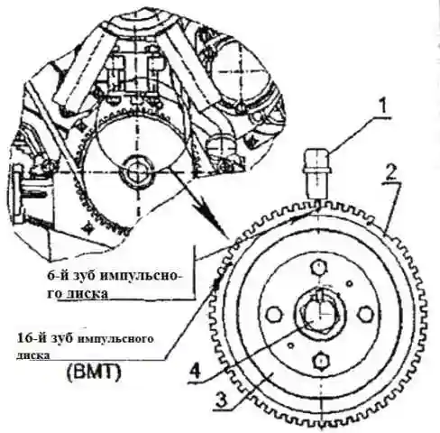
Set the piston of the first cylinder to the TDC position by turning the crankshaft clockwise using bolt 4 (Fig. 2) until the axis of the 16th tooth of the "crown" of the impulse wheel coincides (when counting counterclockwise from the gap segment in " crown" of the impulse wheel) with sensor axis 1.
Make sure the intake and exhaust valves of cylinder 1 are closed.
If the exhaust valve is open, rotate the crankshaft a full turn and recheck the condition of the valves.
Install the piston of the first cylinder on the compression stroke (~ 60° of the crankshaft rotation angle before TDC), for which:
- turn the crankshaft clockwise using bolt 4 (Fig. 3) approximately two turns
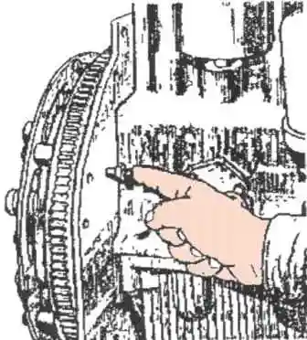
- at the same time, on the second turn, turn it out in accordance with fig. 2 latch from the threaded hole of the rear sheet, insert it with the reverse side into the same hole until it stops into the flywheel (for ZIL diesel engines, press the spring-loaded latch all the way into the flywheel) and turn the crankshaft until the latch coincides with the hole in the flywheel;
In this case, the impulse wheel 2 (Fig. 3), fixed on the crankshaft pulley 3, will be located in such a way that the axis of the sensor 1 will pass along the axis of the sixth tooth of the "crown" of the impulse wheel (when counting counterclockwise from the break segment in " crown" impulse wheel).

In case of misalignment of the sensor and the sixth tooth, it is necessary to loosen the sensor fastening and achieve the coincidence of the axes of the sensor and the tooth, and fix the sensor.
On the removed gearbox, turning the drive coupling half clockwise 5 (Fig. 5) (in Figure 4 the gearbox is shown with the gearbox drive gear installed on the drive coupling half), achieve a position in the window for installing the sensor of two successively located impulse pins.
Slightly turn the drive in the opposite direction to position the dowel pin (the first one in the direction of shaft rotation) in the center of the window.
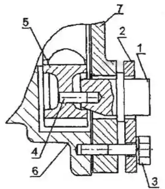
Install the fixture in the window to fix the position of the locating pin 1 (Fig. 5) and secure the fixture with the mounting flange 2 and bolts 3.
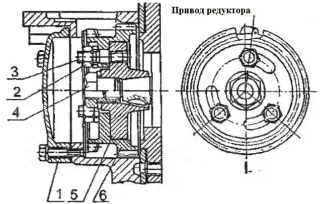
Remove the manhole cover 1 (Fig. 6) and, supporting the drive gear 6 through the hatch window, insert the half-coupling of the drive 5 into the grooves of the drive gear of the pin 3, thus installing the gearbox.
Fix the reducer in the switchboard.
Install and tighten nuts 2 to 35-50 Nm.
Remove the mounting flange and remove the mounting tool.
Replace the mounting flange and secure it.
Install the manhole cover, speed sensor and secure them.
Remove the flywheel retainer and thread it into the rear sheet.
Install the cylinder head cover cap