


The exhaust gas recirculation system reduces the toxicity of the exhaust gases.
Through the recirculation system, part of the gases returns to the cylinders for afterburning.

The main element of the system is the valve, which at high crankshaft speeds lets the exhaust gases through into the intake tract for afterburning. The valve body is aluminium, the heat exchanger is of stainless steel plate type; the flanges are sealed with metal gaskets, and the cooling unions are hoses with spring clips.
Before entering the intake, the exhaust gases are cooled in the recirculation system cooler.
Removing the valve and cooler of the recirculation system
We disconnect the battery negative terminal.
For convenient access, we remove the air filter.
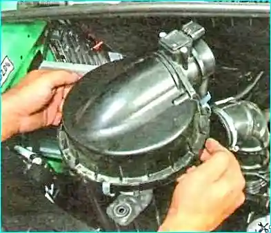
We remove the air supply hose.

We drain the coolant from the engine cooling system.

We disconnect the harness connector from the valve electric actuator connector.

We undo the bolt securing the bypass pipe to the bracket on the engine.

We undo the two bolts securing the pipe to the intake pipe.

We undo the two bolts securing the pipe to the recirculation valve.

We remove the bypass pipe.

The flange securing the pipe to the intake pipe is sealed with a rubber ring.

We squeeze the securing clip, slide it along the hose and disconnect the heater fluid supply hose from the pipe.

We undo the bolt securing the bracket of the engine cooling system pipes.

We disconnect the cooling system pipes from the heat exchanger unions.

We undo the two bolts securing the valve to the exhaust manifold.

We undo the nut of the cooler securing clip.

We spread the clip and remove the exhaust gas recirculation valve together with the cooler.

We remove the sealing gasket.

We refit the recirculation valve together with the cooler in the reverse order.
Tightening torques of the bypass pipe bolts:
- on the intake manifold — 10 N·m;
- on the recirculation valve — 24 N·m.
We fill the engine coolant and bleed the air locks.