
The system consists of a fuel supply system, which includes a fuel tank, a fuel filter with a booster pump, a high-pressure fuel pump, injectors, and fuel lines.
The system also includes an air supply system, which consists of an air filter, a turbocharger, an intercooler, and an intake pipe.
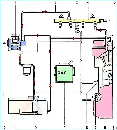
Common Rail engine fuel system
A fuel intake with a coarse mesh filter is installed in the stamped steel tank.
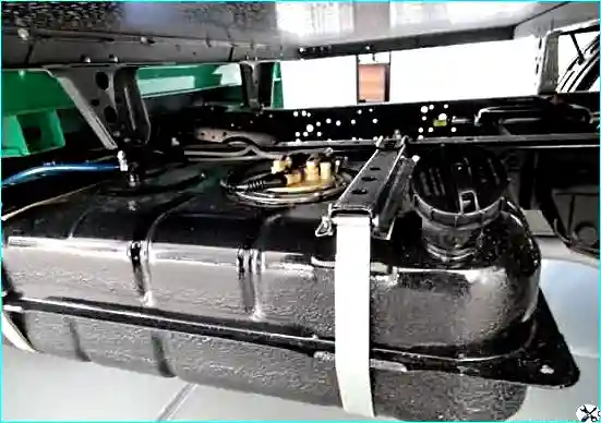
The fuel tank is installed on the frame.
Fuel is fed from the tank through a pipeline through a fine filter to the high-pressure fuel pump (HPFP). From the pump, fuel under high pressure enters the rail, from which it is supplied to the injectors.
The fuel intake is attached to the tank with a clamping ring with screws through a rubber sealing ring.
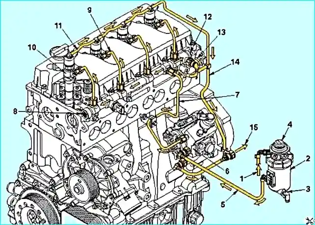
The high-pressure pump supplies fuel to the common high-pressure fuel line regardless of the engine speed.
High-pressure fuel accumulates in this fuel line, from where it is constantly supplied to the injectors.
The ECM regulates the fuel supply and injection timing by switching on the injectors.
In this pump, the fuel pressure increases to a level of 250 - 1600 bar in three radial pumping chambers.
The actuator valve of the electronic fuel supply system, installed at the inlet to these chambers, regulates the volume of fuel entering them.
To do this, it uses signals from the ECM, which maintains the pressure in the common high-pressure fuel line at the required level.
Fuel that does not enter the pumping chambers exits through the cascade bypass valve.
It directs part of the fuel under pressure into the channels of the high-pressure pump lubrication system and then ensures that the fuel is drained into the tank.
The fuel rail accumulates fuel and distributes it between the fuel lines of individual injectors.
A sensor is installed in the rail that monitors the pressure created in it by the high-pressure pump.
The signal from this sensor is used by the ECM to regulate the supply of the high-pressure fuel pump. In addition, there is a pressure-reducing valve in the common fuel line.
It functions as a safety valve, releasing excess pressure if the pressure in the fuel line exceeds the set level.
The fuel drained from the common high-pressure fuel line returns to the fuel tank through the drain fuel line.
The high-pressure fuel pump is driven by gears from the rear end of the crankshaft.
A mechanical booster pump is also installed in the pump housing, which ensures the suction of fuel from the tank.
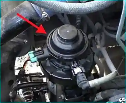
The fine fuel filter with a replaceable filter element assembled with a fuel booster pump is designed to clean the fuel in the engine fuel system from mechanical impurities and water.
It is located in the engine compartment on the left side of the frame side member.
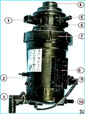
The filter housing has an air outlet hole closed with a bolt, a mesh filter for preliminary fuel cleaning and a tap for draining sediment (water).
To prevent clogging of the filter in cold weather, an electric fuel heater is built into the filter housing.
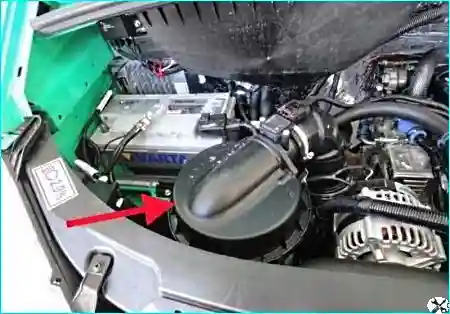
The air filter is installed on the right side of the engine compartment.
In the air filter, air entering through the air intake, is filtered, passing through the curtains of the filter element.
Then, through the branch pipe in the upper part of the filter housing, the air enters the engine turbocharger via the air duct.
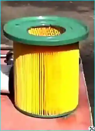
Air filter element with a large filtration area.
The filter element is made of porous cardboard.
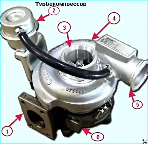
The turbocharger is installed on the exhaust manifold and is designed to improve the filling of the cylinders by using the energy of the exhaust gases.
The turbocharger consists of a single-stage compressor and a radial turbine.
The principle of operation of the turbocharger is that the exhaust gases from the cylinders under pressure enter the gas turbine chamber through the exhaust manifold.
Expanding, the gases rotate the turbine wheel.
The rotation is transmitted through the shaft to the compressor wheel, which sucks in air, compresses it and delivers it under pressure to the engine cylinders.
The turbine wheel is cast from a heat-resistant alloy and welded to the shaft.
The compressor wheel is cast from an aluminum alloy and secured to the shaft with a special nut.
The turbocharger shaft bearing is lubricated with oil supplied under pressure through a pipeline from the oil pump.
From the turbocharger, oil is drained through a pipe into the engine crankcase.
The turbocharger is equipped with gas-oil contact seals with spring rings.
On the turbine side, the sealing rings are installed in the groove of the sleeve pressed onto the rotor shaft, and on the compressor side - in the groove of the compressor sleeve.
To improve the efficiency of the oil seal on the compressor side, the sealing ring area is separated from the area of active oil ejection from the bearing by an oil deflector, which forms an additional labyrinth.
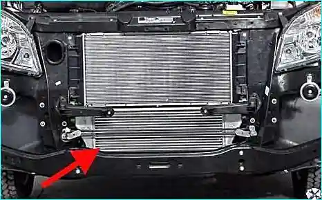
The charge air cooler (intercooler) is a tubular-ribbon aluminum, installed below the radiator of the engine cooling system.
Before entering the engine intake pipe, the air passes through the cooler, which is connected by air ducts to the turbocharger and the intake pipe.
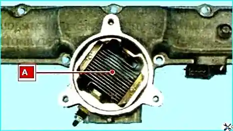
To make it easier to start the engine, an electric heater "A" is built into the intake pipe.
When you turn the key in the ignition, the heater turns on and the light on the instrument panel lights up, after it goes out, you can turn on the starter.
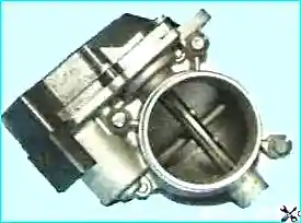
The throttle assembly is a housing with a valve that is controlled by an electric drive from a signal from an electronic pedal.
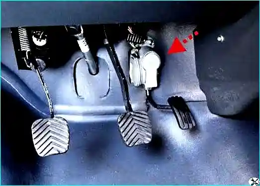
The electronic valve control pedal (gas pedal) is bolted to the front panel.