The car is equipped with two independent brake systems: working and parking.
The first, equipped with a hydraulic drive, provides braking when the car is moving, the second slows down the car in the parking lot
The working system is two-circuit, with a diagonal connection of the brake mechanisms of the front and rear wheels.
One hydraulic circuit provides the right front and left rear brakes, the other - the left front and right rear.
If one of the circuits of the service brake system fails, the second circuit is used to stop the car with sufficient efficiency.
A vacuum booster is included in the hydraulic drive
An anti-lock braking system (ABS), an electronic brake force distribution system (EBD) and a dynamic stabilization system (DSC) are installed on the car.
Parking brake system with cable drive to the brake mechanisms of the rear wheels from the floor lever, with signalization.
The brake mechanism of the front wheel is disc, ventilated with automatic adjustment of the gap between the pads and the disc 7 (Fig. 1), with a floating caliper.
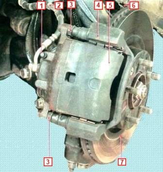
The movable bracket is formed by a caliper 5 with a single-piston working cylinder
The 4 shoe guide is attached with two bolts to the steering knuckle
The movable bracket is bolted to the guide pins 3 installed in the holes of the guide shoe
Guide pins 3 are lubricated with grease and protected with rubber boots
A piston with a sealing ring is installed in the cavity of the working cylinder.
Due to the elasticity of this ring, an optimal gap is maintained between the pads and the brake disc 7, the surface of which is protected by the brake shield 6
When braking, the piston, under the influence of fluid pressure, presses the inner pad against the disc as a result of the reaction force, the caliper 5 moves on the fingers 3 and the outer pad is also pressed against the disc, while the pressing force of the pads is the same.
When releasing the piston, due to the elasticity of the sealing ring, it is retracted from the pad - a small gap forms between the pads and the disc.
The brake mechanism of the rear wheel is disc, non-ventilated, with automatic adjustment of the gap between the pads and the disc 10 (Fig. 2), with a floating caliper.
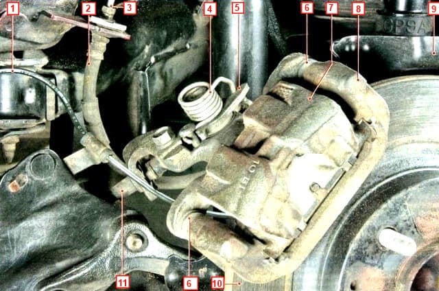
The design of the rear wheel brake mechanism is in many respects similar to the design of the front wheel brake mechanism and differs only in the dimensions of the parts.
The main difference is that the parking brake drive mechanism with lever 5 is built into the rear wheel brake mechanism, to which the rear parking brake drive cable 11 with return spring 4 is attached.
The movable bracket is formed by a caliper 7 with a single-piston working cylinder.
The pad guide 8 is attached with two bolts to the rear suspension knuckle.
The movable bracket is bolted to the guide pins 6 installed in the holes of the guide shoe
The guide pins 6 are lubricated with grease and protected by rubber boots.
A piston with a sealing ring is installed in the cavity of the working cylinder.
Due to the elasticity of this ring, the optimal clearance between the pads and the brake disc 10 is maintained, the surface of which is protected by the brake shield 9
When braking, the piston, under the influence of fluid pressure, presses the inner pad against the disc, as a result of the reaction force, the caliper moves on fingers 6 and the outer pad is also pressed against the disc, while the pressing forces of the pads are the same
When releasing the piston, due to the elasticity of the sealing ring, it is removed from the pad, a small gap forms between the pads and the disc
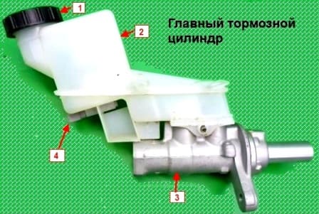
The main brake cylinder 3 (fig. 3) of the tandem type of the hydraulic brake drive consists of two separate chambers connected to independent hydraulic circuits.
The first chamber is connected to the right front and left rear brakes, the second to the left front and right rear.
A tank 2 is installed on the main cylinder through rubber connecting bushings, the internal cavity of which is divided into three compartments by partitions.
Each compartment feeds one of the brake master cylinder chambers and the clutch release master cylinder (if the vehicle is equipped with a manual transmission).
When you press the brake pedal, the pistons of the main brake cylinder begin to move, the working edges of the cuffs block the compensation holes, the chambers and the reservoir are separated, and the displacement of the brake fluid begins
The 4th brake fluid level sensor is installed in the lower half of the reservoir body.
When the fluid level drops below the permissible level, the indicator of a malfunctioning brake system lights up in the instrument cluster.
A vacuum booster installed between the pedal mechanism and the main brake cylinder, when braking due to vacuum in the engine intake manifold through the rod and piston of the first chamber of the main cylinder, creates an additional force proportional to the force from the pedal.
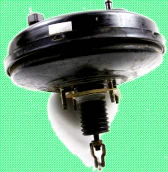
A non-return valve is installed in the hose connecting the vacuum booster to the engine intake manifold.
It holds the vacuum in the booster if it drops in the intake manifold when the engine operating modes change, and after it stops.
The parking brake, actuated mechanically, consists of a lever mounted on the base of the body between the front seats, a front cable with an adjusting device and an equalizer, to which two rear cables 11 are connected and expanding levers 5 of the brake mechanisms of the rear wheels
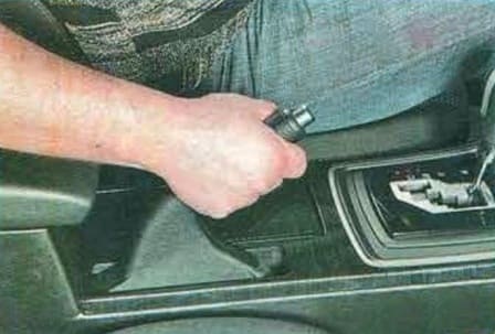
The parking brake mechanism acts directly on the service brake pads.
Moving, the levers of the 5 mechanisms of the parking brake drive move the pistons of the brake cylinders, and through them - the internal brake pads until they stop at the brake discs and then, having received a hard stop, move the calipers together with the outer pads, also pressing them against the discs and blocking the discs.
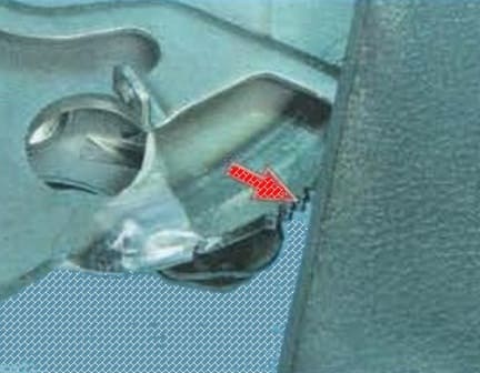
The parking brake requires little maintenance. During the current repair, check the degree of wear of the teeth of the sector and the pawl.
If worn, replace the parking brake lever assembly.
If a breakage of shells or wires is detected, the cables must be replaced with new ones.
The hydraulic brake system is integrated into a single unit with metal pipes and hoses.
The system is filled with a special brake fluid of at least DOT-4 class, which must be replaced periodically
Some drivers, in an effort to reduce wear on the parking brake cables, try to use it less often.
Such "economy" leads to the opposite result: the cable, rarely moving in the shell, gradually loses its mobility, it jams, as a result it breaks.
Therefore, use the parking brake whenever necessary.
If the brake pedal always starts to vibrate when braking, the brake discs are most likely warped.
Unfortunately, in such a situation, they only need to be changed, and both at once in front or behind.
Pedal vibration that appears and disappears periodically during hard braking accompanies the operation of the anti-lock brake system and is not a sign of a malfunction.
If the car starts to pull to the side when braking, check the slave cylinders: they may need to be replaced.
If a knock appears in the front and rear suspensions that disappears when braking, check the tightening of the caliper mounting bolts.
Checking the effectiveness of the brake system
It is necessary to check the efficiency of the brake system on special brake stands (similar to those used during the annual technical inspection of cars).
To do this, contact a service station that has the required equipment, since it is impossible to independently check (on a horizontal platform, by accelerating and braking) the efficiency of the brake system of vehicles equipped with ABS.
Checking and adjusting the position of the brake pedal
The correct position of the brake pedal in the free state and when it is pressed all the way (pedal travel) is one of the criteria for checking the brake system.
At the same time, the position of the pedal largely ensures the correct operation of the system.
If the pedal is at a distance from the floor that is greater than the standard, the wheels may not fully release when the pedal is released (usually there is no free play of the pedal).
If the pedal is set too low, there may be reduced brake performance due to reduced pedal travel.
The position of the pedal is adjusted by changing the distance between the mating surface of the vacuum brake booster and the center of the hole in the fork of its pusher.
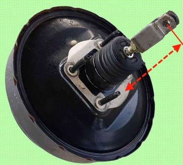
You will need: a ruler, a 17 key. To check the brake pedal, follow these steps.
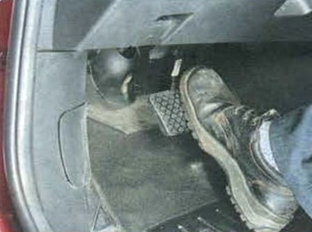
Start the engine, let it idle, and depress the brake pedal vigorously several times.
Pull the brake pedal up as far as it will go with your hand.
Release the pedal and measure the distance from the pedal pad to the floor (maximum pedal travel), the distance should be approximately 128.5 mm.
The ruler must be set perpendicular to the floor plane.
Depress the brake pedal firmly and measure the distance from the pedal pad to the floor (minimum pedal travel), the distance should be approximately 68 mm.
Release the pedal and re-measure the distance from the pedal pad to the free floor.
The pedal should return to its original position by the distance measured in step 3 from the pedal pad to the floor.
Check the free play of the brake pedal by moving the pedal by hand until the pedal stops moving without resistance.
Determine the value of the free play on the ruler, it should be 0-3 mm.
The discrepancy between the free play and the specified range of values can be caused by the following reasons:
- - increased play in the connection of the pusher fork of the vacuum booster and the pedal. This may be due to wear on the fork pin;
- - sticking pistons in the main brake cylinder;
- - plunger jamming in the brake booster.
If the distance from the pedal pad to the floor when re-measured is less than the value measured, then this indicates the pedal is stuck on the axle, the pistons in the working and master cylinders are jammed, or the compensation holes in the brake master cylinder are clogged.
Compensation holes in the main brake cylinder can be blocked by cuffs swollen due to ingress of petroleum products into the system, as well as due to the use of low-quality brake fluid.
Stopping the pedal when pressed almost at the very floor indicates the presence of air in the hydraulic brake drive or the wear limit of the brake pads, brake discs.
If there is air in the system, the pedal stops farther from the floor (“inflates”) with a few repeated presses.
If the pedal is pressed all the way down and held in this position gradually moves to the floor, fluid has leaked from the hydraulic drive or the brake master cylinder is faulty.
These malfunctions are very dangerous, so find the leak immediately and fix it or replace the brake master cylinder!
To adjust the brake pedal, follow these steps.
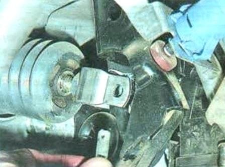
Disconnect the vacuum booster from the brake pedal by pulling your finger out of the fork and pedal holes
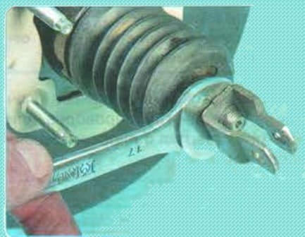
Loosen the locknut (shown on the removed brake booster for clarity) and rotate the vacuum booster rod to adjust the maximum and minimum brake pedal travel.
After adjusting the position of the brake pedal, tighten the locknut, then attach the vacuum booster pusher fork to the brake pedal
Checking the tightness of the hydraulic drive of the brake system
To prevent sudden failure of the brake system, carefully check the condition of all pipelines.
The frequency of checking the brake system is shown in the table. Replace parts with new ones if there is the slightest doubt about their suitability.
Brake fluid is very hygroscopic - it absorbs moisture from the air, which, in addition to causing corrosion of parts of the brake system, lowers the boiling point of the fluid itself, and this can lead to brake failure during frequent heavy braking.
We therefore recommend changing the brake fluid at least once every 2 years
Check the tightness by visual inspection:
- - top from under the hood;
- - from below the car (on a lift or an inspection ditch);
- - from the sides of the car with the wheels removed.
Inspect the part of the hydraulic drive working under pressure with an assistant.
He should depress the brake pedal four or five times (in order to pressurize the hydraulic actuator) and keep it depressed until you inspect the hydraulic actuator.
Inspection of a non-pressurized hydraulic actuator is acceptable, but less effective.
If there is a leak in the connections, tighten the clamps, plugs, nuts.
Replace hoses and pipelines with mechanical damage.
If the slave cylinders are leaking, repair or replace them.
You will need: a special wrench for pipe nuts or a “14” wrench, a flat-blade screwdriver, pliers.
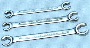
This is how special wrenches for pipe fastening nuts look like.
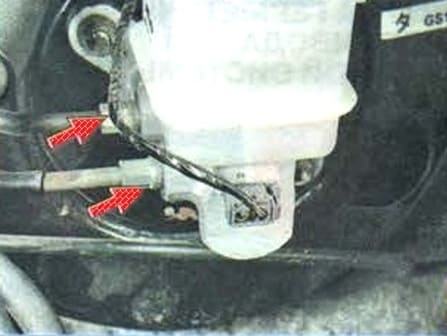
Inspect the reservoir and brake master cylinder, pipe connections to the master cylinder.
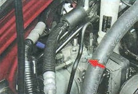
Inspect the piping connection to the anti-lock brake system (ABS) hydro-electronic unit.
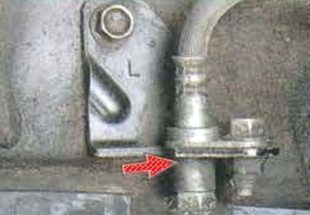
Check for fluid leaks from the front and rear brake hose connections.
Inspect the brake hoses carefully. They should not have cracks, tears or scuffs.
Depress the brake pedal all the way: if swelling appears on the hose, it means that the threads of the hose braid have broken and it must be replaced.
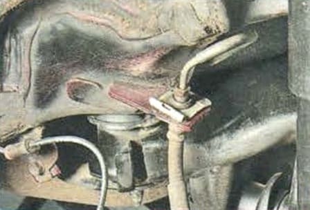
Inspect the hose connections to the working cylinders and the front and rear wheel brake bleed valves.
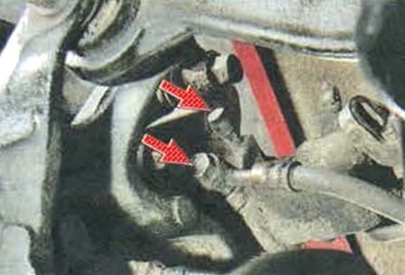
Check the condition of the plastic pipe holders.
Replace damaged holders, as their looseness or breakage leads to vibration and, as a result, to breakage of pipelines.
Possible malfunctions of the brake system and solutions
Increased brake pedal stroke
- fluid leakage from working brake cylinders
Replace bad cylinders, wash and dry pads and discs
- air in the brake system
Bleed the brake system
- the rubber sealing rings in the main brake cylinder are damaged
Replace the brake cylinder in collection
- damaged brake hoses
Replace defective hoses and bleed the brake system
- increased runout of the brake disc (more than 0.1 mm)
Grind or replace the brake disc if the thickness of the brake discs of the front wheels is less than 23.8 mm and the rear wheels are less than 8.0 mm
Insufficient braking performance
- lubrication of linings of brake pads
Rinse and dry the pads
- jamming of pistons in working cylinders
Replace damaged parts
- complete wear of the brake pads
Replace brake pads
- brake overheating
Stop and let the brakes cool down
- use of low quality brake pads
Replace pads
- violation of the tightness of one of the circuits (accompanied by the failure of the brake pedal)
Replace damaged parts, bleed the system
- violation of the adjustment of the vacuum brake booster rod
Adjust the vacuum booster rod
- Violation of the anti-lock braking system (ABS)
Check the anti-lock system
Sliding or pulling the car to the side when braking
- brake cylinder piston jamming
Check and fix the stuck piston in the cylinder
- clogging of a tube due to a dent or blockage
Replace or clean the tube
- contamination or oiling of discs and brake pads
Clean the brake parts
- the wheel alignment angles are violated
Adjust wheel alignment
- different tire pressure
Set the required tire pressure
- one of the circuits of the brake system does not work (accompanied by a decrease in the efficiency of the brakes)
Replace damaged parts. If this does not lead to the desired result, check ABS
Incomplete release of all wheels
- there is no free play of the brake pedal
Check the mobility of the brake pedal
- increased protrusion of the vacuum brake booster rod
Adjust the vacuum booster rod
- swelling of the rubber seals of the main brake cylinder due to the ingress of gasoline, mineral oils, etc. into the liquid.
Replace the rubber parts. Flush and bleed the entire brake system
- master cylinder piston jamming
Check and if necessary replace the brake master cylinder
Braking one wheel when the pedal is released
- piston jamming in the working cylinder due to contamination or corrosion of the body
Replace the slave cylinder and bleed the hydraulic brake
- Swelling of the sealing rings of the working cylinder due to foreign impurities entering the liquid
Replace the slave cylinder and bleed the brakes
- violation of the position of the brake caliper relative to the brake disc when the fastening bolts are loosened
Tighten the mounting bolts, replace damaged parts if necessary
- incorrect adjustment of the parking brake system
Adjust the parking brake
- malfunction of the anti-lock braking system ABS
Check the anti-lock system
Increased effort on the brake pedal when braking
- defective vacuum booster
Replace amplifier
- the hose connecting the vacuum booster and the engine intake manifold is damaged, or its fastening is loose
Replace hose or check valve
- swelling of the rubber seals of the cylinders due to the ingress of gasoline, mineral oils, etc. into the liquid.
Replace cylinders, flush and bleed the system
Squeak or vibration of the brakes
- oiling friction linings
Scrape the pads with a wire brush using water and detergent. Eliminate the causes of fluid or grease on the brake pads
- wear of linings or foreign inclusions in them
Replace pads
- excessive runout or uneven wear (felt by the vibration of the brake pedal) of the brake disc
Grind or replace the disc if the thickness of the front brake discs is less than 23.8 mm and the rear wheels are less than 8.0 mm


