On-board DC network with a nominal voltage of 12 V
Electrical equipment is made according to a single-wire circuit: the negative terminals of sources and consumers of electricity are connected to the "ground" - the body and power unit of the car, which act as a second wire.
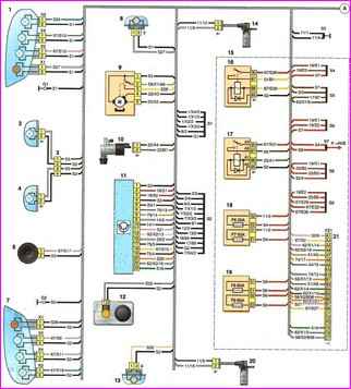
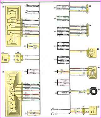
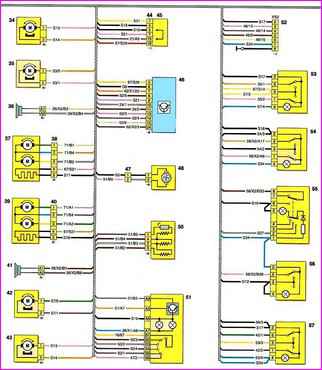
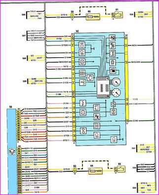
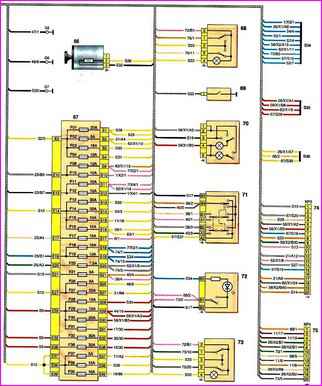
The diagram is divided into five parts. Each scheme corresponds to the numbering of the parts included in the scheme.
A - the place where the wiring harness goes from the engine compartment to the passenger compartment; 1 - right block headlight; 2 - right fog lamp; Z - block connection with a wiring harness for fog lights; 4 - left fog lamp; 6 - sound signal; 7 - left block headlight; 8 - right side direction indicator; 9 - windshield wiper; 10 - windshield washer; 11 - ABS control unit; 12 - brake fluid level sensor; 13 - left side direction indicator; 14 - speed sensor of the right front wheel; 15 - relay and fuse block in the engine compartment; 16 - heater fan relay; 17 - fog lamp relay; 18, 19 - fuses in the relay and fuse box in the engine compartment; 20 - speed sensor of the left front wheel; 21 - connection block with engine wiring harness;
Continued from 1 Front Body Wiring Diagram
22 - right stalk switch; 23 - driver's airbag; 24 - spiral cable; 25 - left stalk switch; 26 - audio system pads; 29 - brake signal switch; 30 - rear window heating relay; 31 - immobilizer coil; 32 - block connection with the wiring harness of the ignition switch; 33 - ignition switch; 34 - electric lock of the right front door; 35 - power window right front door; 36 - right front speaker; 37— right outside mirror; 38 - connection block with the right exterior mirror; 39 - left exterior mirror; 40 - connection block with the left exterior mirror:
Continued 2 Front Body Wiring Diagrams
41 - left front speaker; 42 - power window left front door; 43 - electric lock of the left front door; 44 - diagnostic block; 45 - cover of the diagnostic block with a jumper; 46 - airbag control unit; 47— block connection with the wiring harness of the heater fan; 48 - heater fan; 50 - block of additional heater fan resistors; 51 - control unit for ventilation, heating and air conditioning; 52 - connection block with the front passenger airbag wiring harness and glove box lighting: 53 - power window switch of the right front door; 54 - central locking switch; 55 - alarm switch; 56 - rear window heating switch; 57 - power window switch of the left front door;
Continued 3 Front Body Wiring Diagrams
58 - switching unit; 59 - block connection with the heater harness of the right front seat; 60 - heating element of the right front seat; 61 - switch for heating the right front seat; 62 - instrument cluster; 63 - a block of connections with a harness for heating the front seats; 64 - heating element of the left front seat; 65 - left front seat heating switch; 66 - cigarette lighter; 67 - fuse box in the cabin
Continued 4 Front Body Wiring Diagrams
68 - right rear door power window switch; 69 - switch of the signaling device for turning on the parking brake and a malfunction of the brake system; 70 — dome interior lighting; 71 - regulator for controlling the electric drives of the exterior mirrors; 72 - rear window lock switch; 73 - power window switch of the left rear door; 74, 75 - connection pads with the rear wiring harness of the body
A diagram of the rear of the body wiring harness is located in the article - Nissan Almera Body Rear Wiring Diagram


