


To avoid damaging the contact disc under the steering wheel, the following instructions must be observed:
- before disconnecting the steering shaft from the steering rack, lock the steering wheel and the wheels in the straight-ahead position using the special tool; they must remain locked throughout the entire procedure;
- if the contact disc centring has been performed incorrectly, remove the steering wheel to re-centre it.
This operation must only be carried out by experienced technicians who have received specific training.
Place the vehicle on a two-post lift.
Remove the battery cover.
Disconnect the leads from the battery terminals, starting with the negative terminal.
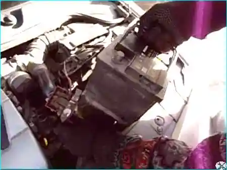
Fig. 1. Removing the battery
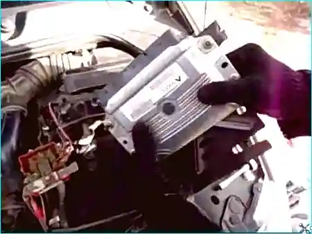
Fig. 2. Removing the engine control unit
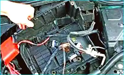
Fig. 3. Removing the battery tray
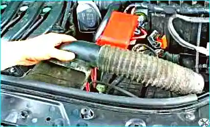
Fig. 4. Removing the air intake hose
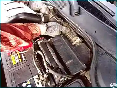
Fig. 5. Loosen the clamps and remove the air duct from the air filter to the throttle body
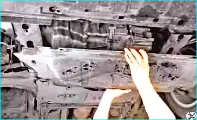
Fig. 6. Remove the engine under-tray and splash shield
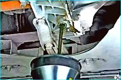
Fig. 7. Drain the oil from the gearbox
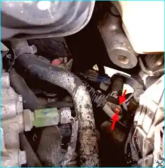
Fig. 8. Release the gear selector cable end clip
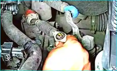
Fig. 9. Disconnect the selector cable end from the gearbox selector lever
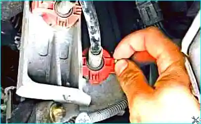
Fig. 10. Disconnect the gearshift cable end as well
Remove the retaining clip.
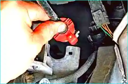
Fig. 11. Move the selector cable away from the bracket. Also move the gearshift cable away from the bracket
Unscrew the earth cable retaining bolt on the gearbox.
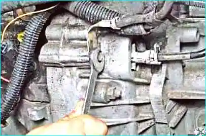
Fig. 12. Unscrew the earth cable retaining bolt on the gearbox
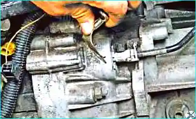
Fig. 13. Move the earth cable aside
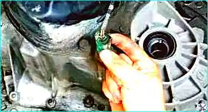
Fig. 14. Release the reverse light switch connector clip
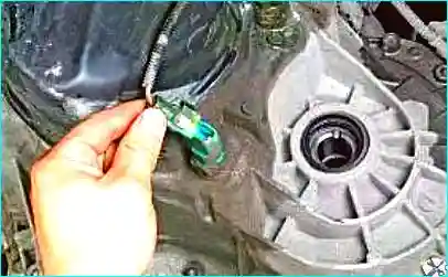
Fig. 15. Disconnect the connector from the switch
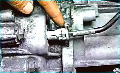
Fig. 16. Release the clutch pipe retaining clip
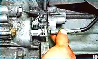
Fig. 17. Disconnect the pipe from the clutch slave cylinder
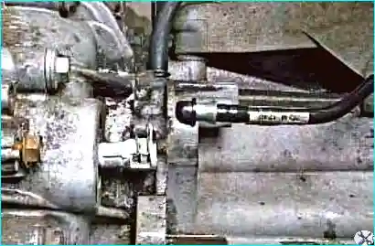
Fig. 18. Remove the protective cap from the clutch bleed nipple and use it to plug the pipe to prevent dirt ingress
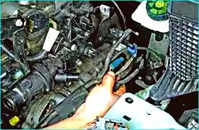
Fig. 19. Remove the engine harness from its retainer on the gearbox and move it aside
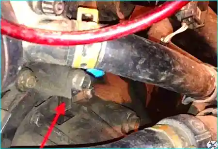
Fig. 20. Disconnect the crankshaft sensor connector
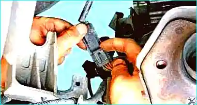
Fig. 21. Release the oxygen sensor connector clip
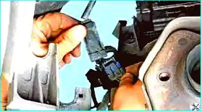
Fig. 22. Disconnect the connector from the harness
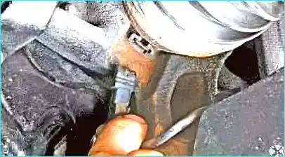
Fig. 23. Disconnect the wheel speed sensor connector
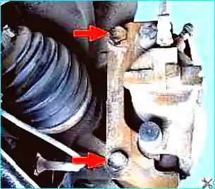
Fig. 24. Remove the front wheels and unscrew the two brake caliper fixing bolts from the steering knuckles
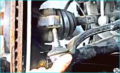
Fig. 25. Move the calipers aside and secure them with wire or hooks to the front suspension springs
Disconnect the track rods from the steering knuckles.
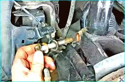
Fig. 26. Unscrew the shock absorber fixing nuts (one on each side) and remove the bolts from the knuckles
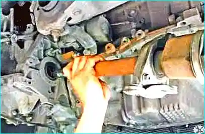
Fig. 27. Move the steering knuckles aside and disconnect the inner joints of the drive shafts from the gearbox
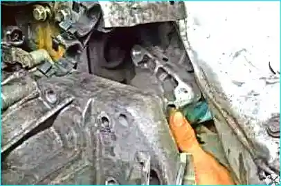
Fig. 28. Remove the starter motor
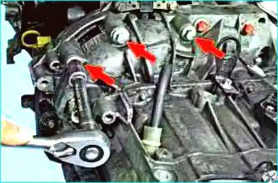
Fig. 29. Unscrew the three upper gearbox-to-engine fixing bolts
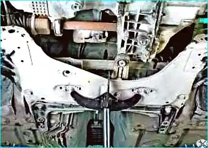
Fig. 30. Remove the subframe. During this process, disconnect the rear engine mount from the gearbox
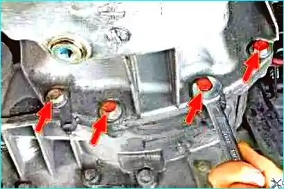
Fig. 31. Unscrew the four oil pan-to-clutch housing fixing bolts
Place secure supports under the engine and the gearbox.
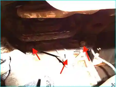
Fig. 32. Unscrew the three gearbox housing-to-left engine mount fixing bolts
Slide the gearbox rearwards until the clutch housing dowels are clear of the cylinder block holes.
The gearbox input shaft must disengage from the clutch driven disc hub.
Slide the gearbox back as far as possible, remove the support from underneath, and tilt the rear of the gearbox downwards to remove it from the vehicle.
Take care not to rest the gearbox input shaft against the clutch cover diaphragm fingers to avoid deforming them.
Installation
Do not apply lubricant to the gearbox input shaft to avoid damaging the clutch slave cylinder and the input shaft splines.
To prevent fluid leaks, always replace the clutch slave cylinder when replacing the clutch cover.
Ensure that the locating dowels are present and correctly positioned to align the engine and gearbox.
Installation is carried out in the reverse order of removal.
During installation, tighten the clamp bolt of the steering shaft universal joint yoke.
Tighten to the specified torque:
- wheel bolts (110 N·m);
- hub nut (280 N·m);
- suspension arm ball joint nut (62 N·m);
- track rod end ball joint nut (37 N·m);
- stabiliser link ball joint nut (44 N·m);
- side panel retaining bolts (2 N·m);
- gearbox and starter-to-engine bolts (44 N·m);
- torque reaction rod-to-engine bolts (180 N·m);
- torque reaction rod-to-subframe bolts (105 N·m);
- gearbox pendulum support bolts (62 N·m);
- pendulum support-to-mounting bush nut (180 N·m);
- clamp bolts of the universal joint yoke (21 N·m);
- front radiator crossmember bolts (105 N·m);
- rear radiator crossmember bolts (210 N·m);
- subframe crossmember bolts (62 N·m);
- rear subframe bolts (140 N·m);
- link rod-to-subframe bolts (105 N·m);
- gearbox drain plug (25 N·m);
- gearbox fill plug (3 N·m).
Fill the gearbox with oil.
Bleed the clutch hydraulic system as follows:
- top up the brake fluid reservoir;
- bleed the clutch system;
- top up the brake fluid to the correct level.
Connect the leads to the battery terminals, starting with the positive terminal.


