


Removing and refitting the intake manifold (K4J engine)
Precautions: disconnect the leads from the battery terminals, starting with the negative terminal.
Preliminary operations:
- Remove the air filter housing.
- Remove the throttle body.
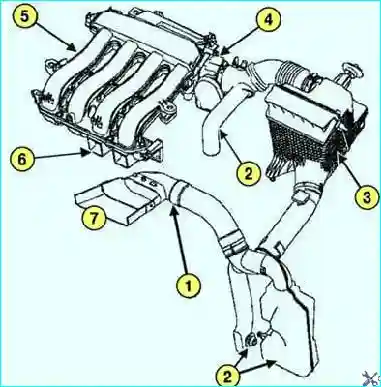
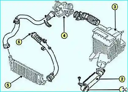
Removal procedure
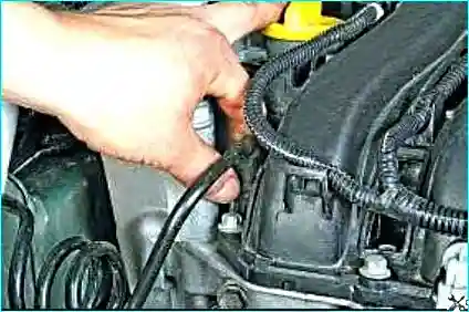
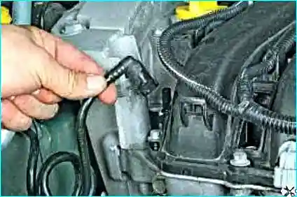
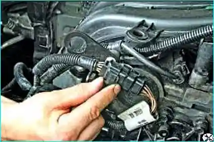
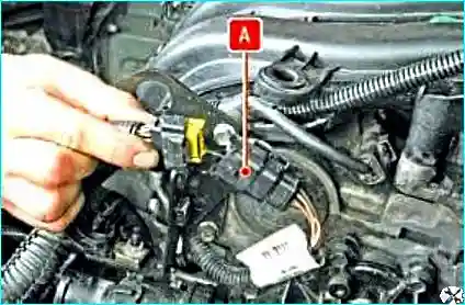
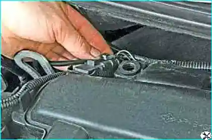
Press the retainer of the wiring harness connector of the pressure sensor in the receiver. Disconnect the connector from the sensor.
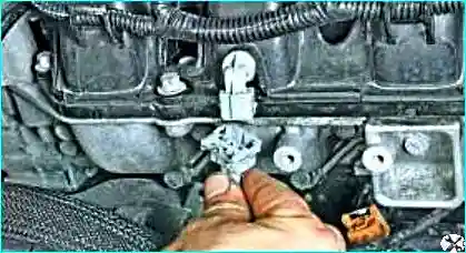
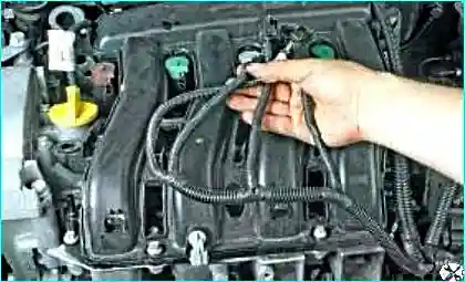
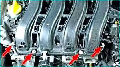
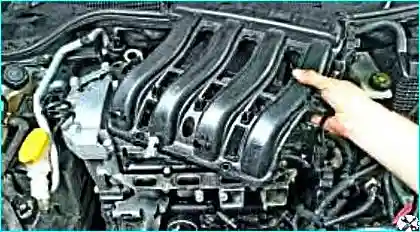
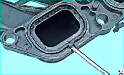
Note: prise up the sealing rings with a screwdriver and remove them. When refitting, replace the sealing rings.
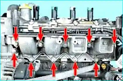
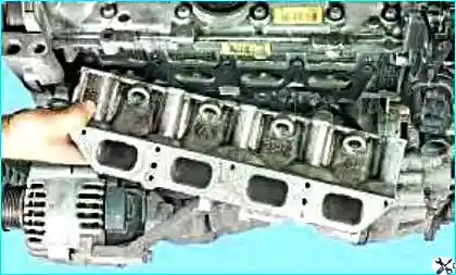
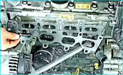
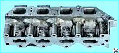
Refitting
Important! All sealing gaskets are subject to mandatory replacement.
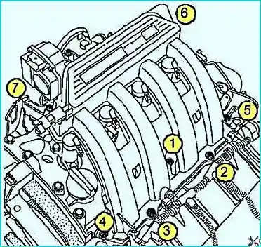
Refitting is carried out in the reverse order to removal. Tighten in the sequence shown in Fig. 5 to the required torque the intake manifold securing bolts:
- intake manifold securing bolts — 9 N·m;
- throttle body securing bolts — 13 N·m;
- air filter housing securing bolts — 9 N·m.
Reconnect the leads to the battery terminals, starting with the positive terminal.
Removing and refitting the intake manifold (K4M, F4R engines)
Precautions: disconnect the leads from the battery terminals, starting with the negative terminal.
Preliminary operations:
- Remove the upper engine covers.
- Remove the air duct.
- Disconnect the wiring connector from the throttle body.
- Disconnect the brake servo vacuum hose from the intake manifold.
- Disconnect the fuel vapour recovery system pipeline from the throttle body.
- Disconnect the wiring harness and move it aside.
- Disconnect the fuel supply pipe from the fuel distribution rail.
- Disconnect the fuel vapour control system pipeline from the intake manifold.
Attention: do not damage the vacuum take-off stub on the intake distribution manifold. If the stub is broken, replace the manifold.
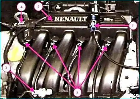
Unscrew the intake manifold securing bolts. Remove the throttle body.
Important! All sealing gaskets are subject to mandatory replacement.
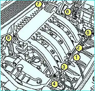
Refitting is carried out in the reverse order to removal. Tighten in the sequence shown in Fig. 7 to the required torque:
- intake manifold securing bolts — 9 N·m;
- throttle body with servo drive securing bolts — 13 N·m (uniformly and alternately).
Reconnect the leads to the battery terminals, starting with the positive terminal.
Removing and refitting the exhaust manifold (K4J, K4M engines)
Precautions: place the vehicle on a two-post lift. Disconnect the leads from the battery terminals, starting with the negative terminal.
Preliminary operations:
- Remove the air filter housing (K4J).
- Remove the intake manifold (K4M).
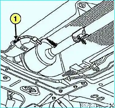
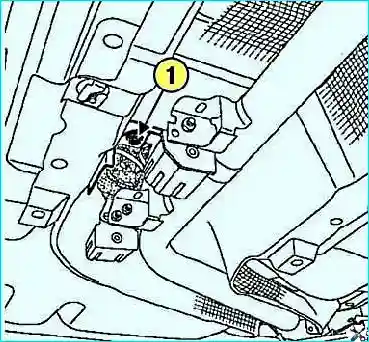
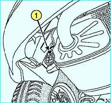
Mark with a marker the position of the exhaust pipeline suspension cushion brackets on the body.
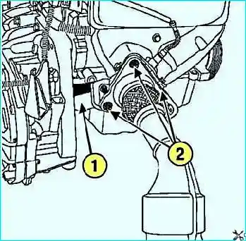
Move the exhaust pipeline rearwards. Remove the oxygen sensor using the tool (Mot1495-01).
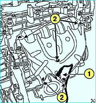
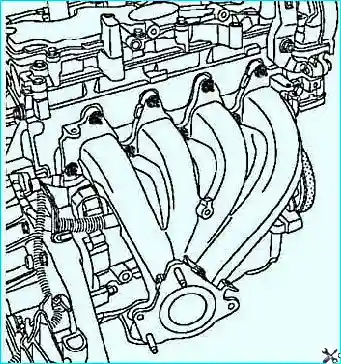
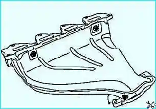
Subject to mandatory replacement:
- manifold gaskets;
- exhaust pipeline flange gaskets;
- nuts of the exhaust manifold securing studs.
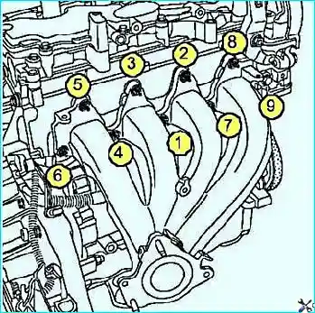
Refitting is carried out in the reverse order to removal. Tighten in the sequence shown in Fig. 15 to the required torque:
- nuts of the exhaust manifold securing studs — 23 ± 3 N·m;
- heat shield securing bolt — 10 N·m;
- oxygen sensors — 45 N·m;
- bolts securing the exhaust pipeline suspension cushion brackets to the body — 21 N·m;
- strut securing bolt on the exhaust manifold — 8 N·m;
- exhaust pipeline flange securing nuts — 20 N·m.
Reconnect the leads to the battery terminals, starting with the positive terminal.
Removing and refitting the exhaust manifold (F4R engine)
Precautions: disconnect the leads from the battery terminals, starting with the negative terminal. Remove the power unit and the turbocharger.
Important! When removing and refitting the turbocharger, the repair procedure must be strictly followed to ensure the tightness of the system. Failure to follow these instructions may result in reduced driver safety.
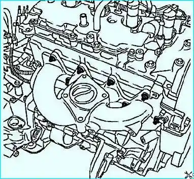
Unscrew the nuts of the securing studs and remove the exhaust manifold.
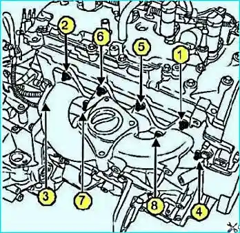
Refitting is carried out in the reverse order to removal. Tighten in the sequence shown in Fig. 17 to the required torque of 20 N·m the nuts of the exhaust manifold securing studs.
Refit the turbocharger and the power unit.


