We remove the steering column switches for replacement, as well as when removing the steering column and instrument panel.
Preparing the car. Disconnect the negative battery terminal.
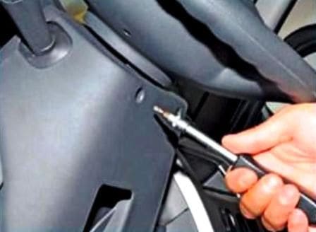
Using a Torx T-20 wrench, unscrew the two screws securing the steering column covers
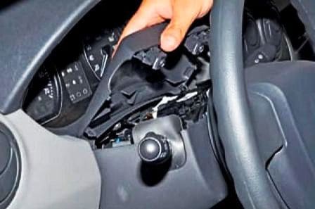
Remove the upper casing of the steering column
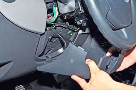
Remove the lower casing of the steering column, disengaging the casing hook
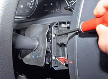
We unscrew the two screws securing the steering column switch
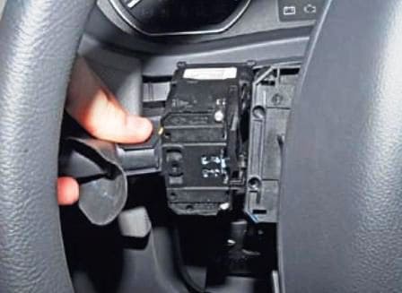
Remove the switch from the connector socket
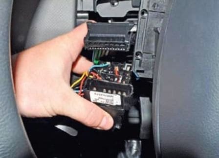
Disconnect the wire block from the switch. We also remove the second steering column switch
Install switches and all parts in reverse order
Removing the switch assembly with connector
Disconnect the negative battery terminal
Removing the steering wheel (article - How to remove the steering wheel of a Renault Sandero )
Remove the steering column cover as described above
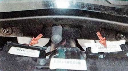
Disconnect the wire pads from the steering column switches
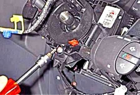
We unscrew the screw of the clamp fastening the connector
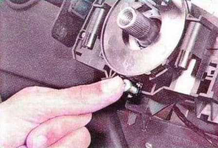
And press on the screw to loosen the clamp
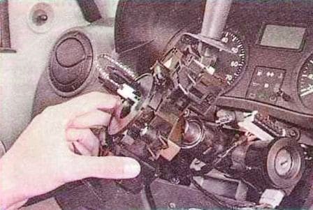
Remove the connector assembly with steering column switches
Install parts in reverse order
Steering column check
We determine the serviceability of the steering column switches by checking the correct closure of the contacts at various positions of the levers
Remove the switches for testing and connect a 12 volt test lamp with a current source or a tester with a continuity function to the appropriate terminals indicated in the tables
We move the switch lever to the position corresponding to the contacts being checked - the lamp should light up. Otherwise, the switch is defective.
The pin numbers are shown in figure 1 and 2.
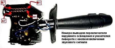
Contact closure at different positions of the outdoor lighting switch lever and direction indicators with the horn button
Switched on device - Numbers of closed contacts
- Left turn signal - A7-A6
- Right direction indicator - A5-A6
- Marker light - B1-B2
- Switching low / high beam - B5-B3
- High beam headlights - B5-B3 + B7-B6
- Front fog lights - A1-B2 + B1-B2
- Rear fog light - A3-B2 + B1-B2
- Beep - A4-B6
Contact closure at different positions of the windshield wiper and washer switch lever with the button for switching display modes of the on-board computer
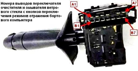
Switched on device - Numbers of closed contacts
- Windscreen washer pump - A4-B4
- Slow wiper speed - A3-A7
- High wiper speed - A2-A7
- Intermittent wiper - A1-A7 + A3-A6
- Intermittent wiper, low speed - A3-A6
- Button for switching display modes of the on-board computer - A4-B7


