Remove the transfer case and clean it of dirt
Drain the oil from the transfer case.
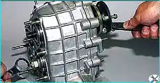
Loosen the nuts of the three flanges of the transfer case shafts.
Remove the speed sensor drive housing.
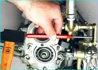
Disconnect the linkage of the differential lock lever from the axis of the fork of the control lever
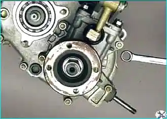
Using a 13 key, we unscrew the five nuts securing the front axle drive housing
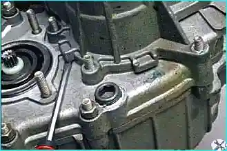
Pry off the crankcase tides with a screwdriver
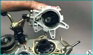
Remove it assembled with the front axle drive shaft
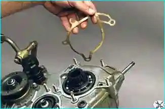
The connection is sealed with a gasket
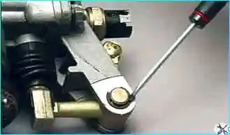
Prying off the lock washer of the locking axis with a screwdriver
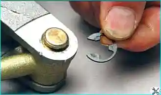
Remove the lock washer.
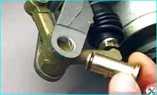
We take out the axle of the differential lock lever (if difficult, we knock it out with a soft metal drift)
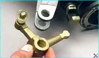
Remove the differential lock lever
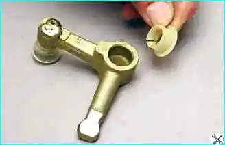
Two plastic bushings are installed in the lever hole
Turn off the differential lock indicator switch.
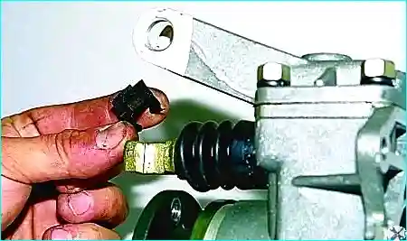
Remove the lever spring from the stem of the differential lock fork
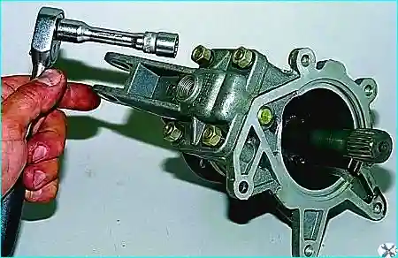
With a 13 head, we unscrew the four nuts securing the front axle drive housing cover.
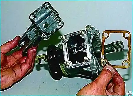
Remove the cover and gasket.
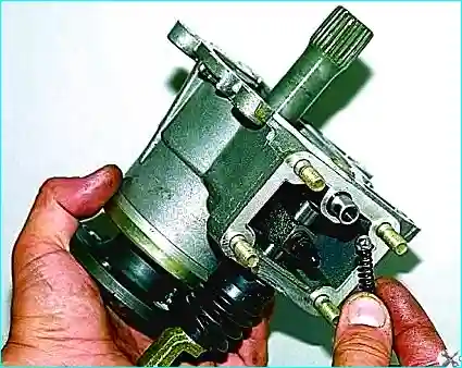
Remove the spring and shake the retainer ball out of the crankcase
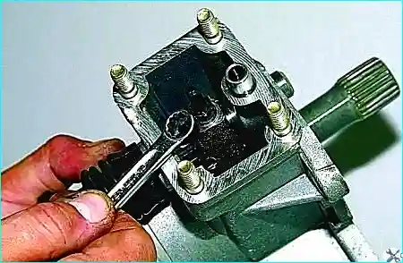
Using a 10 key, we unscrew the locking bolt of the differential lock clutch fork
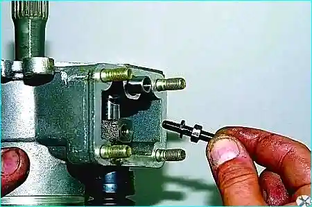
Remove the bolt with spring washer
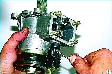
We pry off the protective cover of the differential lock fork rod with a screwdriver
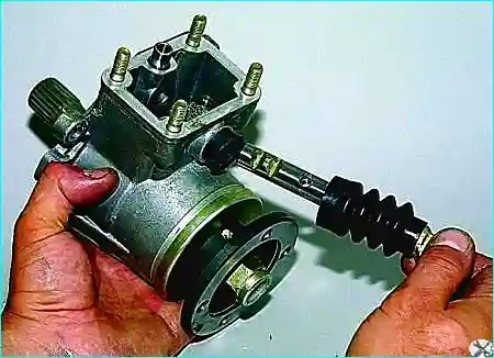
Remove the stock with a cover
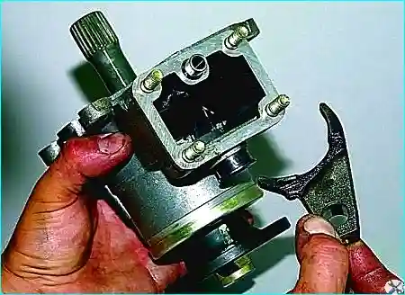
Removing the plug
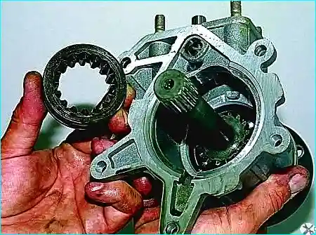
Remove the differential lock
Unscrew the flange fastening nut and remove the washer.
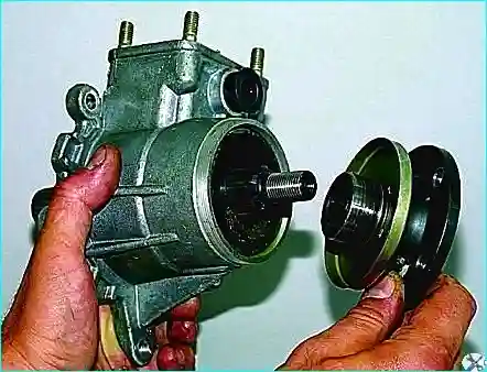
Remove the flange
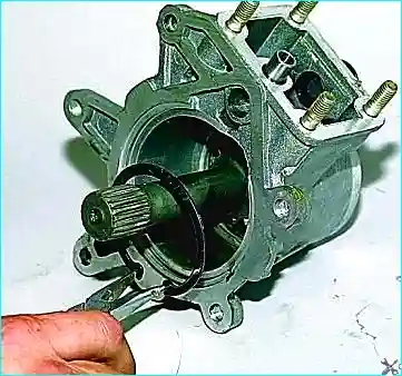
Squeeze with tongs, remove the retaining ring of the front axle drive shaft bearing
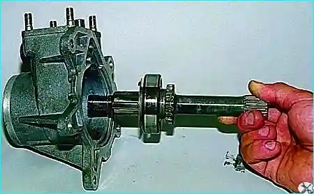
Remove the shaft assembly from the crankcase
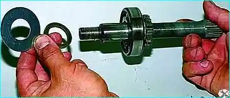
Remove the oil slinger and thrust ring from the front end of the shaft
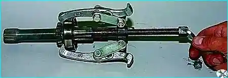
Hooking the outer ring of the bearing with a three-jaw puller
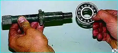
Compressing the bearing
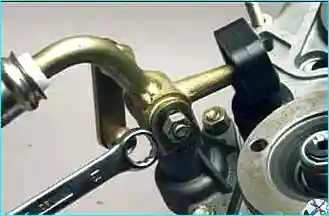
Using a 13 key, we unscrew the nut of the control lever axis
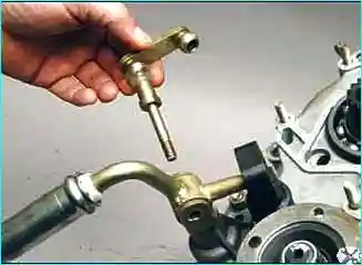
We remove the axis from the hole in the lever along with the rod.
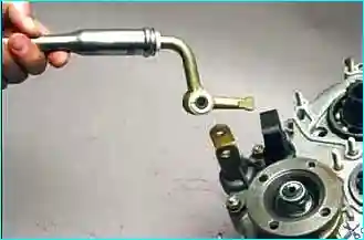
Remove the control lever.
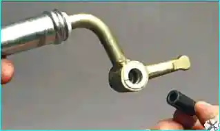
Remove the spacer sleeve from the lever hole
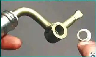
Remove two plastic bushings
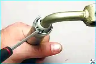
Using a screwdriver, we remove the petals of the locking sleeve from the groove lever rod
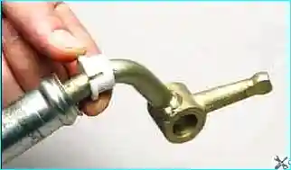
Remove the sleeve from the lever rod
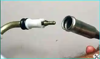
Remove the lever rod
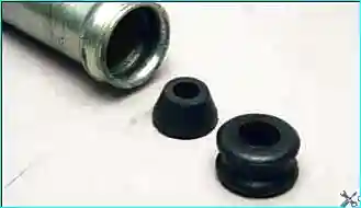
The parts of the transfer case should be labeled or stacked in order on the racks.
Having prying with a screwdriver, we remove the rubber bushing and thrust pad from the hole in the rod.
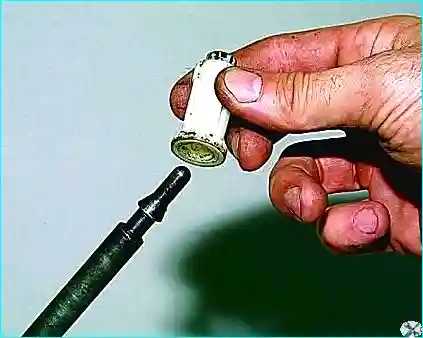
Opening the petals of the remote sleeve, remove it from the lever
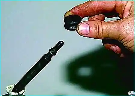
Remove the rubber bushing from the lever
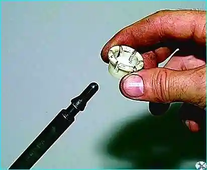
Remove the spacer
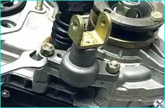
Using a 13 key, we unscrew the two nuts securing the control lever bracket
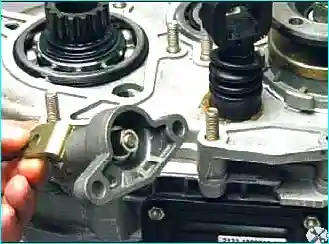
Remove the bracket assembly with the plug
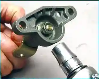
Holding the fork, with a head of 13, unscrew the nut of the fork axis
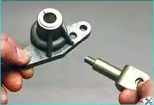
Remove the axle.
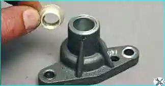
Two plastic bushings are installed in the bracket hole.
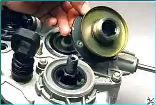
Remove the driveshaft flange nut and remove the washer. Removing the flange
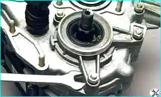
With a 13 key, we unscrew the three nuts securing the drive shaft front bearing cap
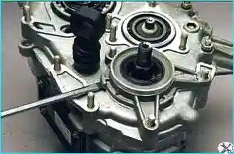
Pry off the tides of the cover with a screwdriver
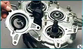
Remove the cover. The cover is installed on the sealant
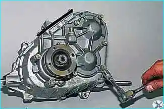
Using a 13 head, unscrew the eight nuts securing the rear cover to the transfer case housing
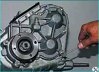
Pry off the cover with a screwdriver
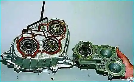
Remove the cover assembly with the rear axle drive shaft
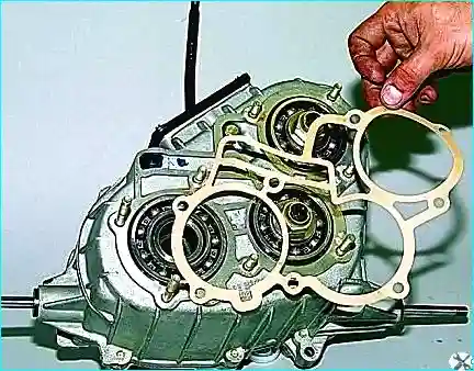
Remove the gasket.
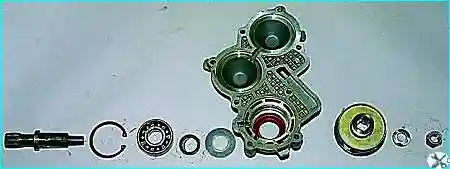
Remove the rear axle drive shaft from the rear cover and disassemble it in the same way as the front axle drive shaft.
Rear axle drive shaft parts and rear cover
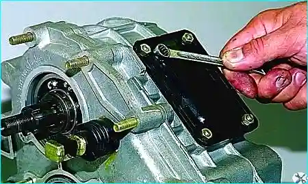
With a head of 10, we unscrew the four nuts securing the hatch
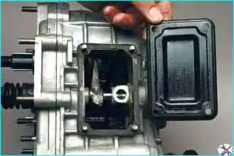
Remove the hatch
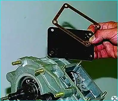
Removing the gasket
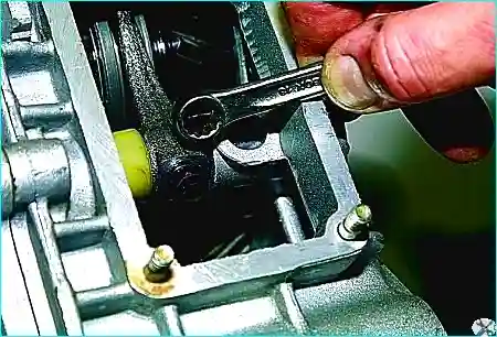
Inside the hatch, use a 10 spanner to unscrew the bolt securing the fork to the stem.
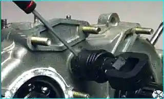
Use a screwdriver to move the stem cover
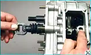
So that the ball and the spring of the latch do not pop out, cover the hole with your finger and gradually pull the stem
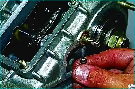
In this case, the lock ball falls out through the opening of the crankcase.
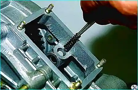
Remove the latch spring with tweezers
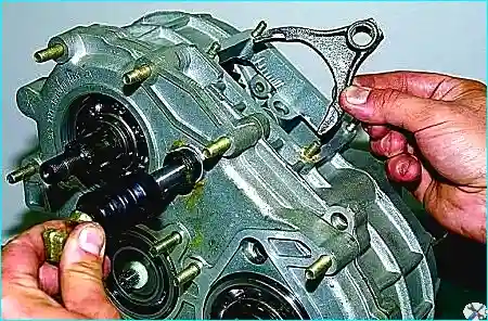
Remove the shift fork
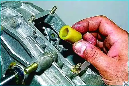
Remove the plastic spacer
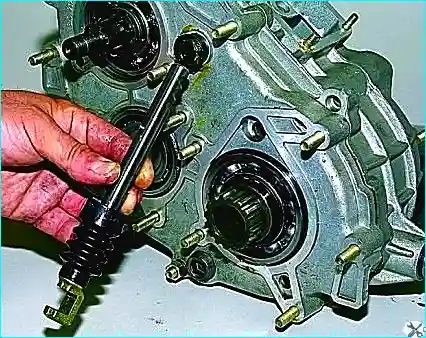
Removing the stem
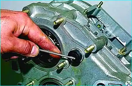
To replace the shift fork rod ring, pry off the O-ring with a screwdriver
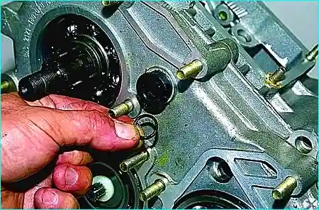
Take out the ring.
Also take out the sealing ring of the differential lock fork rod
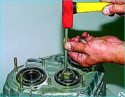
Unlock the nuts of the rear bearings of the drive and intermediate shafts
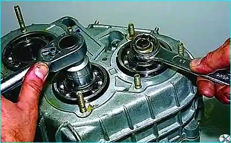
Using a 27 wrench, we unscrew one of the nuts, keeping the shafts from turning by the other nut with a wrench
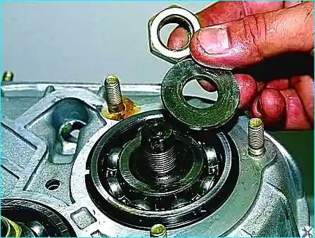
Remove the nut and washer
Insert the propeller shaft mounting bolts into the flange holes and put the flange on the splines of the transfer case drive shaft.
We unscrew the second nut, keeping the shafts from turning with a mounting spatula inserted between the bolts.
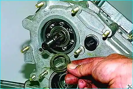
Remove the nut and washer.
Remove the drive shaft flange.
Remove the thrust ring of the front bearing of the input shaft.
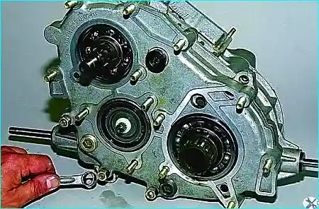
Using a 13 key, we unscrew the three remaining nuts securing the front cover of the box.
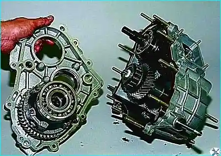
Remove the front cover of the transfer case and differential.
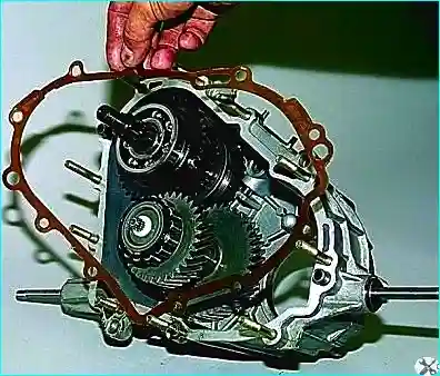
Remove the gasket from the transfer case housing studs
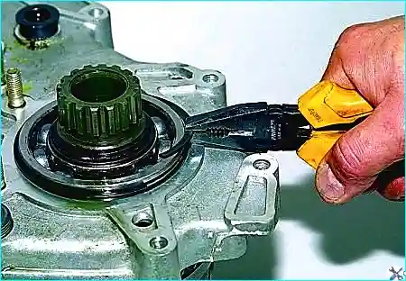
Use pliers to remove the adjusting ring of the front bearing of the differential housing
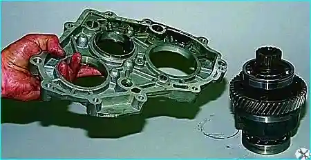
Disconnect the differential and the front cover of the transfer case
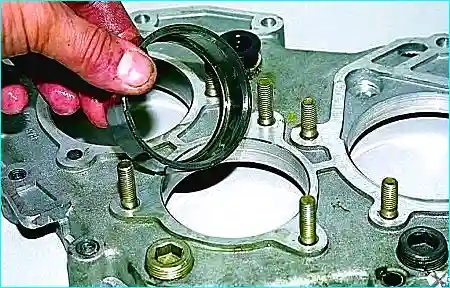
We knock out the outer ring of the front bearing of the intermediate shaft with a soft metal drift
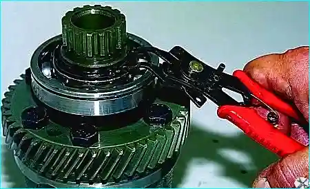
Using pliers, we open the retaining ring of the front bearing of the differential housing
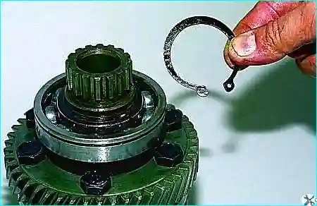
And remove the ring
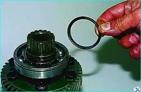
Remove the spring washer.
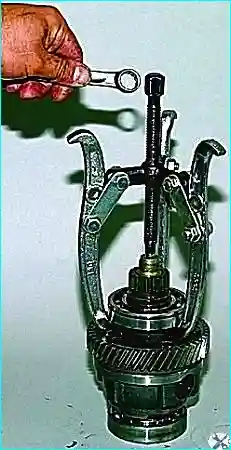
We install a suitable stop for the puller screw and a three-jaw puller in the hole of the front differential housing
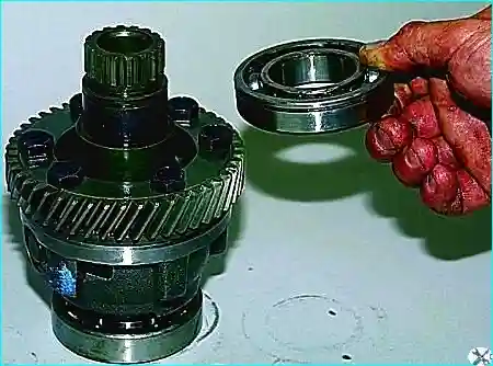
Compressing the front bearing.
Also remove the rear bearing.
We put marks on the front and rear differential housings so that the balance is not disturbed during assembly.
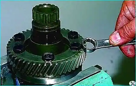
We clamp the differential housing in a vice and with a 17 spanner we unscrew the six bolts securing the driven gear and the differential housing
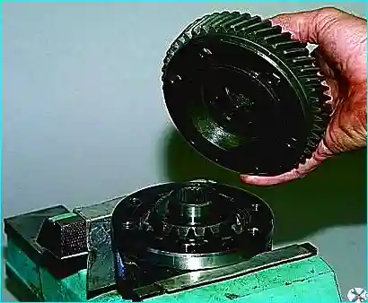
Disconnect the housings, while the driven gear remains on the front housing
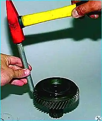
We knock down the gear from the body through a soft metal drift
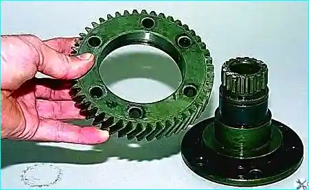
Disconnecting the driven gear and the front differential case
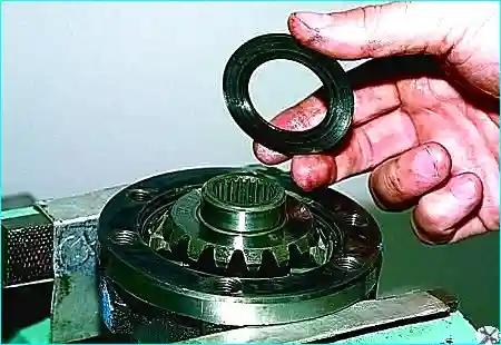
Remove its support washer from the front axle drive gear
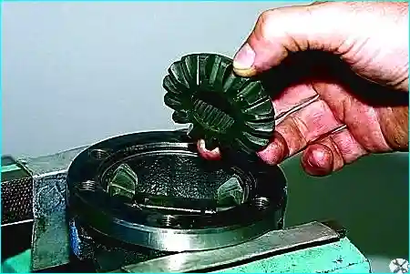
Removing the gear itself
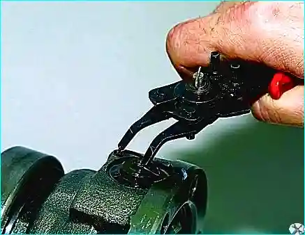
Using pliers, we open the retaining ring of the axis of the satellites and remove it
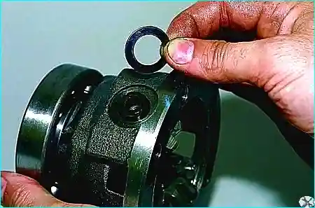
We hook another retaining ring with pliers, take out the axis of the satellites.
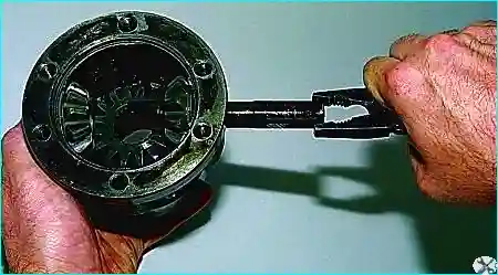
Remove the support washer and satellite from the rear differential case.
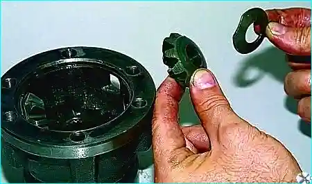
Having removed the second satellite and its washer, we remove the rear axle drive gear.
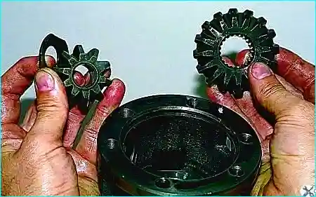
To remove the input and intermediate shafts with pliers, remove the adjusting ring of the rear bearing of the input shaft.
We also dismantle the intermediate shaft rear bearing ring
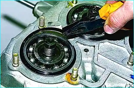
Remove the drive shaft from the crankcase
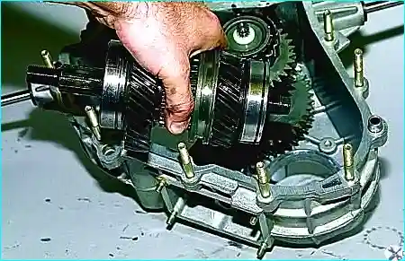
Removing the intermediate shaft
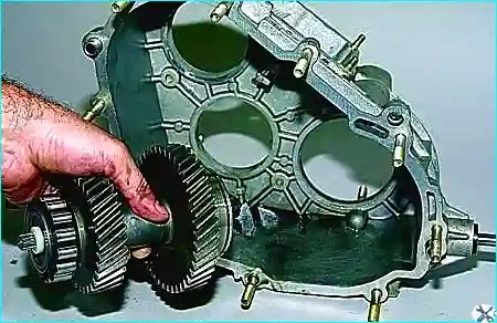
We clamp the splined part of the drive shaft into a vise with soft jaws and, hooking the gear shift clutch with the grips of the puller
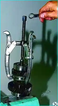
Remove the rear bearing, bushing, low gear and clutch.
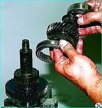
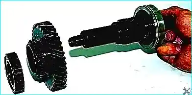
Remove the clutch hub and top gear from the shaft
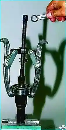
We press the front bearing of the drive shaft with a puller
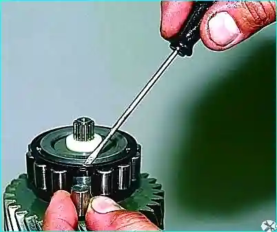
Remove the rollers from the front bearing of the intermediate shaft with a screwdriver
Clamp the intermediate shaft in a vice with soft pads.
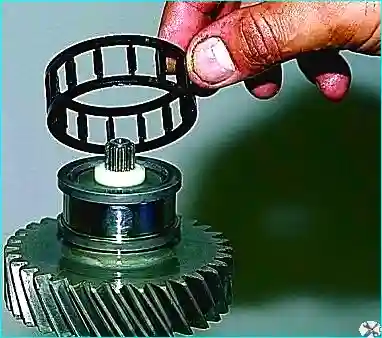
Pry off with two mounting blades, compress the inner ring of the front bearing
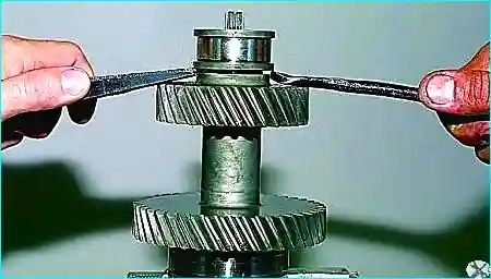
Remove it. We also remove the rear bearing of the intermediate shaft


