Before disassembling, clean the outer surface of the gearbox with a cleaner or solvent.
Clean the removed parts with a solvent and dry with compressed air.
When disassembling, check the condition of the parts for wear and damage.
Only use plastic hammers to separate the crankcase parts.
Do not use rags when disassembling: rag fibers can clog the fluid channels.
Some parts are similar to each other, so when disassembling, arrange them so as not to mix them up.
If the clutch or brake band is burnt or the quality of the fluid in the gearbox has deteriorated, then it is imperative to clean the valve block.
Install the gearbox on a special stand or workbench.
Unscrew the bolts securing the clutch housing to the gearbox housing (Fig. 1)
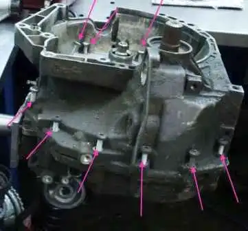
Disconnecting the gearbox housing (Fig. 2)
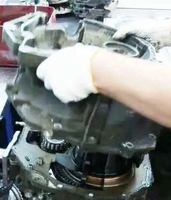
Removing the magnet from the automatic transmission filter (Fig. 3)
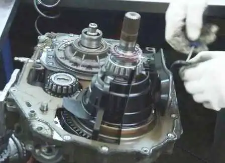
Unscrew the pump (Fig. 4)
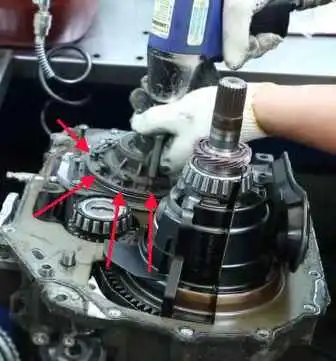
Remove the pump and separate the filter from it (Fig. 5)
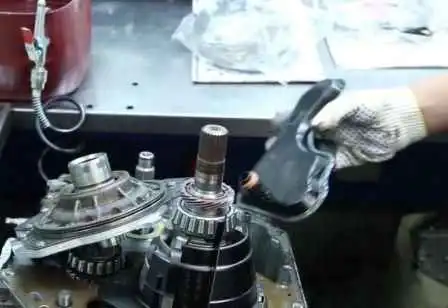
Disassemble the pump, remembering the position of the parts, and determine their wear (Fig. 6)
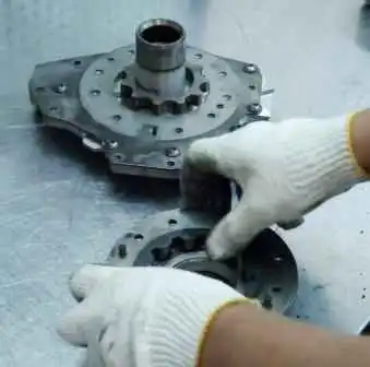
Remove the gearbox housing gasket (Fig. 7)
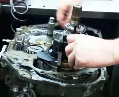
Removing the differential (Fig. 8)
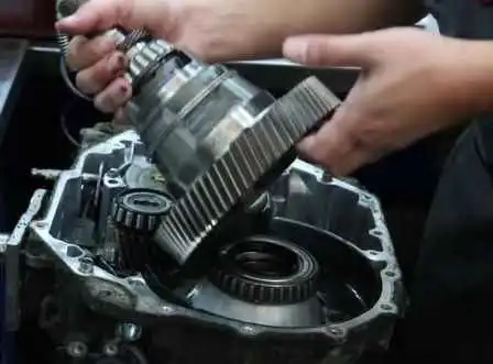
Removing the parking lever (parking pawl) (Fig. 9)
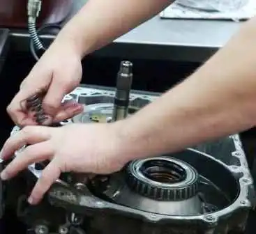
Using thin pliers, remove the brake band servo piston (Fig. 10)
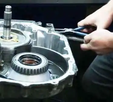
Remove the first and second gear brake band (Fig. 10)
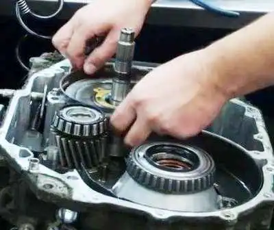
Removing the first and second gear drum (Fig. 12)
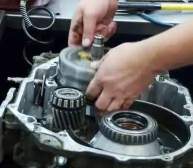
Removing the secondary shaft (idler gear) (Fig. 13)
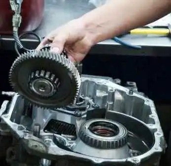
Turn the transmission over and unscrew the valve body pan mounting screws (Fig. 14)
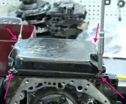
Remove the valve body pan and inspect we check the magnets for chips (Fig. 15)
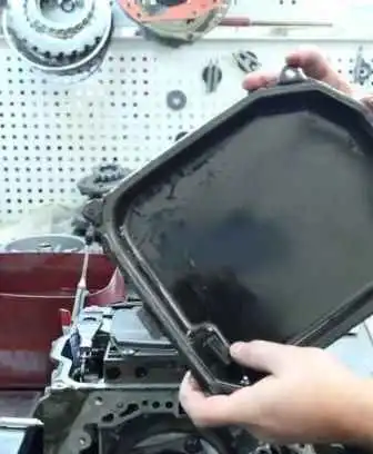
Unscrew the valve body mounting screws (Fig. 16)
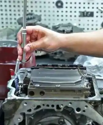
Remove the valve body plate, the valve body itself (Fig. 17) and seals
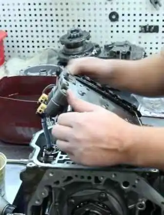
Examine all foreign inclusions and particles found in the pan and on the magnet to determine the condition of the transmission components.
The presence of clutch wear particles indicates wear of the drive plate or brake bands.
Steel particles on the magnet indicate wear of the bearings, gears, or drive plate.
The presence of aluminum particles indicates wear of the bushings or transmission housing.
If there are a large number of foreign inclusions and particles, replace the torque converter and carefully check the condition of the gearbox parts.
Unscrew the rear cover of the gearbox (Fig. 18)
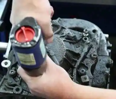
Remove the fourth gear piston (Fig. 19)
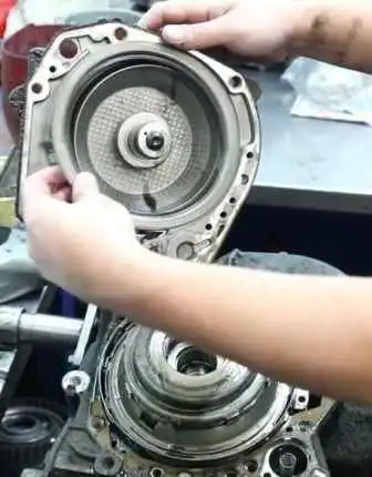
Remove the rear covers (Fig. 20)
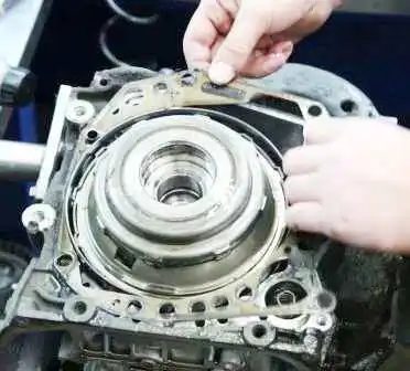
Removing the input shaft (Fig. 21)
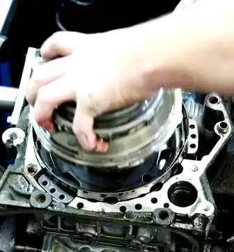
Removing the clutch pack for the second, third and fourth gears (Fig. 22)
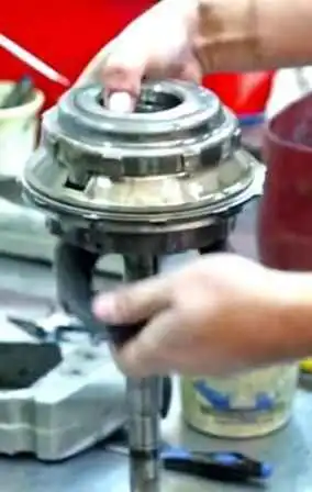
Removing the small sun gear and one-way clutch (HAP) (Fig. 23)
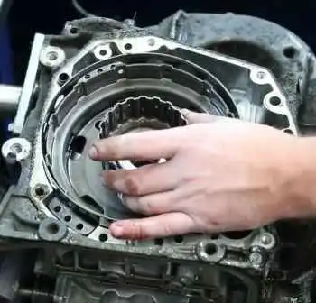
Removing the fourth gear clutch pack (Fig. 24)
Helpful Tips:
If the drive plate or brake band is replaced with a new one, soak the new part in automatic transmission fluid for at least two hours before installation.
Put automatic transmission fluid on all oil seals, rotating parts, O-rings, and moving parts before assembly.
All O-rings, oil seals, and gaskets must be replaced with new ones.
When reassembling, use petroleum jelly, but do not lubricate with consistent grease.
When it is necessary to replace the bushing, replace the part (unit) containing the same bushing.
After applying the sealant, assembly must be carried out within 10 minutes and left for 30 minutes before filling with automatic transmission fluid.
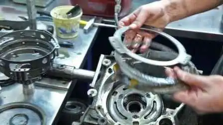
Next, we need to remove the reverse gear servo piston.
To do this, rest the wooden handle of the hammer on the servo piston and squeeze the retaining ring with pliers (Fig. 25)
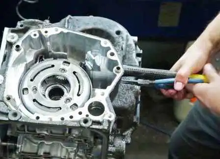
Remove servo piston from the gearbox housing (Fig. 26)
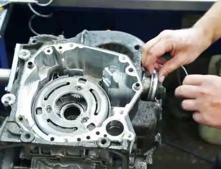
Removing the reverse gear brake band (Fig. 27)
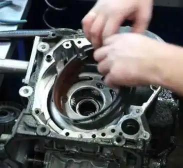
Removing the drum with the planetary block (Fig. 28)
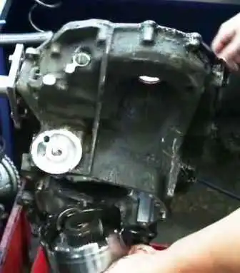
After that, all parts are washed and inspected.
We will consider the assembly of the transmission in the next article.


