Disassembly of the transfer case was discussed in the article Disassembly of the transfer case
Before inspection, thoroughly clean all parts of the transfer case with a brush and scraper, and then wash. Blow off the parts with a jet of compressed air.
Wash and blow out the bearings especially thoroughly, avoiding their rapid rotation from the jet of compressed air to avoid damaging them.
Crankcase and covers
There should be no cracks on the crankcase and covers, no wear or damage (dents, chips) is allowed on the surface of the bearing bores.
Damage to the mating surfaces of the crankcase with the covers can cause shaft misalignment and oil leakage.
File off minor damage.
Replace parts with new ones in case of significant damage or wear.
Oil seals
Check their condition carefully.
Replace oil seals with new ones if even minor damage is detected.
Width The wear of the working edge of the seal should not exceed 1 mm.
Shafts. No damage is allowed on the working surfaces, threaded part and on the splines of the shafts.
Check the runout of the drive shaft and the drive shafts of the front and rear axles by installing them on prisms and turning them manually.
The runout of the end part of the thrust belts for the bearings should be no more than 0.01 mm.
When checking the intermediate shaft, pay attention to the condition of the gear block and the drive pinion of the speedometer drive.
Chipping or excessive wear of the teeth is not allowed. Replace defective parts.
Gears
When inspecting the gears, check the condition of the teeth and seating surfaces.
Teeth chipping and excessive wear are not allowed.
The seating surfaces of the gears should not have any scoring or wear that would cause a large gap.
Check the gap in the gear engagement; The mounting clearance should be 0.10 mm, the maximum allowable is 0.20 mm.
The mounting clearance between the low gear pinion and the bushing, as well as between the drive shaft and the high gear pinion should be 0.05-0.10 mm, the maximum allowable is 0.15 mm.
If wear exceeds the permissible limits, replace the gears with new ones.
Bearings
Ball and roller bearings should not have damage on the raceways of the rings, on the separators, rollers or balls, as well as cracks and chips on the rings.
The radial clearance of the bearings should not exceed 0.05 mm.
When turning, a clean, dry bearing should not knock.
The movement should be smooth, without jamming.
Replace damaged bearings.
Rods, forks
Fork deformation and rod jamming in the crankcase holes are not allowed.
Replace the locking parts with new ones if signs of jamming are detected.
Also replace the locking springs if they have lost elasticity.
The length of the spring under a load of 99.15-114.85 N (10.2-11.8 kgf) should be 19 mm, in a free state - 23.3 mm
Hubs, couplings
Check for signs of jamming on the hub of the gear engagement coupling and, especially, on the sliding surfaces of the couplings, as well as on the splines of the differential housing.
Scuffs and burrs clean with a file.
Pay special attention to the condition of the ends of the clutch teeth; if they are damaged or crushed, which prevents it from moving when shifting, replace the clutch.
Differential
Check the condition of the surface of the satellite axle and the holes in the differential housing; in case of minor damage, sand the surfaces with fine-grained sandpaper, and in case of significant damage, replace the parts with new ones.

Check the condition of the surface of the axle drive pinion journals and their mounting holes in the differential housings, as well as the condition of the bearing surfaces on the adjusting washers and the mating end surfaces on the axle drive housings and pinions.
Remove any damage found with fine-grained sandpaper or a velvet file; replace significantly damaged or worn parts.
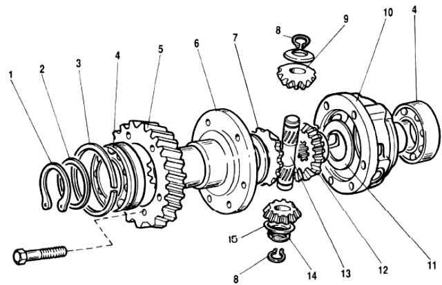
With spring washer 14 removed (see Figure 1), make sure there is no radial movement of the retaining rings 8 in the canavkah axle 13. If play is detected, replace the retaining rings.
Testing the transfer case
Test the assembled transfer case on a stand for noise, build quality and absence of oil leakage.
Carry out the check sequentially in the highest and lowest gears at the following speed of the input shaft in both directions:
- - I mode — 100-200 min¹
- - II mode — 2000-2500 min¹
- - III mode — 3500-4000 min¹
In the second mode, carry out the check without load and under variable torque load, and in I and III modes — without load.
Check the operation of the differential in the first mode, alternately braking the front and rear axle drive shafts until they stop completely.
Shift gears and lock the differential with the transfer case shafts stationary.
The following is not allowed in the transfer case: jamming of both gears and differential lock, knocking or uneven noise of gears and oil leakage.
Assembling the transfer case
Assemble the transfer case in the reverse order according to the article Disassembling the transfer case.
When assembling the center differential, align the marks on its housings.
Install the spring washer on the satellite axle from the side blind hole on the end of the axle.

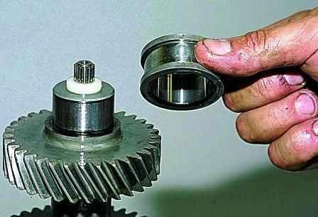
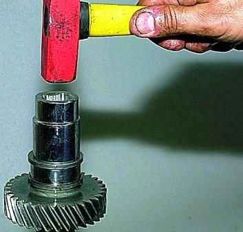
Using pipe sections or tool heads of a suitable size, press on the inner ring of the front bearing of the intermediate shaft.

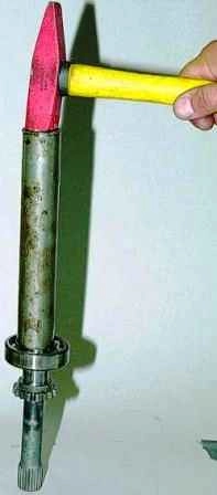
Press on the front axle drive shaft bearing (the pipe should rest on the inner ring).

Press on the differential bearings
In the same way, press on the rear axle drive shaft bearing, the rear bearing of the intermediate shaft, the front and rear bearings of the driving shaft
We install the drive and intermediate shafts into the transfer case housing at the same time.
We apply a thin layer of silicone sealant to all the sealing gaskets.
Having tightened the nuts of the rear bearings of the drive and intermediate shafts to the prescribed torque, we lock the nuts by pressing their flanges into the grooves of the shaft tails.
After assembly, fill in the oil.
Tightening torques for fasteners of transfer case parts
Part - Thread - Torque Nm (kgf.m)
- Nut for fastening the suspension bracket to the cushion axle - M10x1.25 - 26.5-32.3 (2.7-3.3)
- Nut for fastening the suspension bracket to the body - M8 - 15.0-18.6 (1.53-1.90)
- Nut for fastening the transfer case housing covers, front axle drive housing, speedometer drive housing, control lever bracket - М8 - 14.7-24.5 (1.5-2.5)
- Differential lock switch - М16х1.5 - 28.4-45.0 (2.9-4.6)
- Bolt for fastening the forks to the gear shift rods - М6 - 11.8-18.6 (1.2-1.9)
- Bolt for fastening the forks to the differential lock rod - М12х1.25 - 11.7-18.6 (1.2-1.9)
- Bolt for fastening the driven gear - М10х1.25 - 66.6-82.3 (6.8-8.4)
- Nut for fastening the rear bearing of the drive shaft and the rear bearing of the intermediate shaft - М18х1.5 - 96.0-117.6 (9.8-12.0)
- Nut for fastening the flange of the cardan shaft to the drive shaft and to the drive shafts of the front and rear axles - М16х1.5 - 96.0-117.6 (9.8-12.0)


