


The control of the exterior lighting and light signalling, as well as the windscreen wipers and washers, is carried out by means of the steering column switches installed on the steering column.
The left steering column switch combines the switches of the direction indicators, exterior lighting, headlight beam, front fog lights (if installed) and the rear fog light.
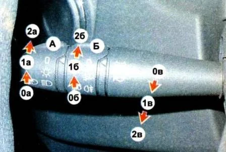
Switch A of the exterior lighting and headlights:
- 0а — exterior lighting and headlights off;
- 1а — exterior lighting on (side lights, number plate illumination) and instrument panel illumination;
- 2а — exterior lighting, dipped or main beam on (if the ignition switch is in position M).
Switch B of the fog lights and the rear fog light:
- 0б — lights and lamp off;
- 1б — lights on, lamp on (the ignition switch is in position M and switch A is in position 1а or 2а);
- 2б — lights and lamp on.
To switch off the fog lights and the lamp it is necessary to turn switch B to position 0б.
Headlight beam switch (moving the lever backwards):
- 0в — dipped or main beam on (if switch A is in position 2а);
- 1в — main beam on while the switch is in this position (regardless of the position of switch A, non-locked position);
- 2в — switching between dipped and main beam (non-locked position), if switch A is in position 2а.
To switch the beam it is necessary to move the headlight beam switch to position 2в.
Direction indicator switch (moving the lever up/down):
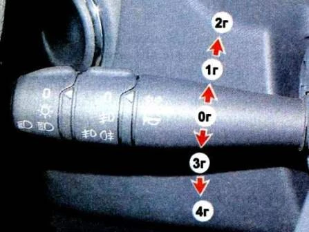
- 0г — direction indicators off;
- 1г — right direction indicator on (non-locked position);
- 2г — right direction indicator on (locked position);
- 3г — left direction indicator on (non-locked position);
- 4г — left direction indicator on (locked position).
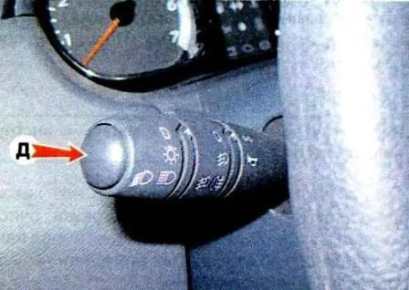
Horn button (д).
To sound the horn it is necessary to press the button on the end of the left steering column switch.
The right steering column switch combines the switches of the operating modes of the front and rear windscreen wiper and washer.
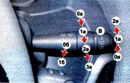
Switch of the operating modes of the front windscreen wiper (moving the lever downwards):
- 0а — windscreen wiper off;
- 1а — intermittent mode of the windscreen wiper on;
- 2а — first speed of the windscreen wiper on;
- 3а — second speed of the windscreen wiper on.
Switch of the front windscreen washer (moving the lever backwards):
- 0б — windscreen wiper and washer off;
- 1б — windscreen washer on (if the windscreen wiper was not on before, it will switch on for three cycles).
Switch (В) of the operating modes of the rear windscreen wiper and washer:
- 0в — windscreen wiper and washer off;
- 1в — windscreen wiper on;
- 2в — windscreen wiper and washer on (non-locked position, if the switch is released, it returns to position 1в).
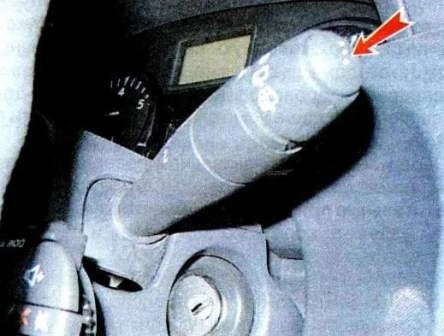
On the end of the right steering column switch is located the information display control button.
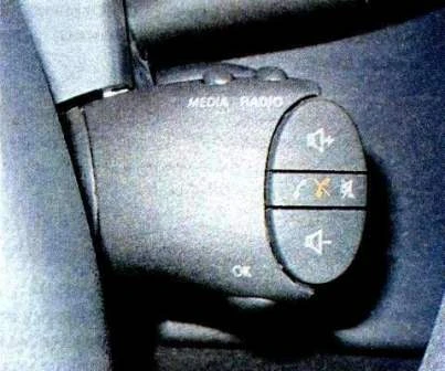
Under the right steering column switch may be located the switch of the operating modes of the audio system.
Removing and installing the steering column switches
We disconnect the negative terminal of the battery.
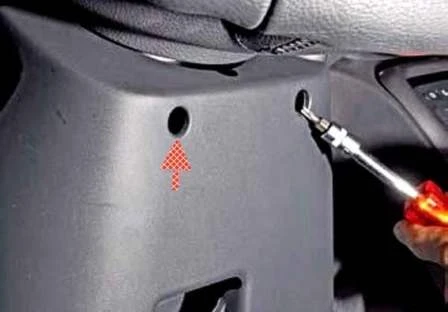
With a Torx T-20 key we unscrew two screws securing the steering column shrouds.
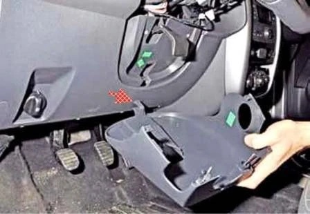
We remove the lower steering column shroud, disengaging the shroud hook (shown by the arrow).
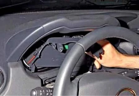
We remove the upper steering column shroud.
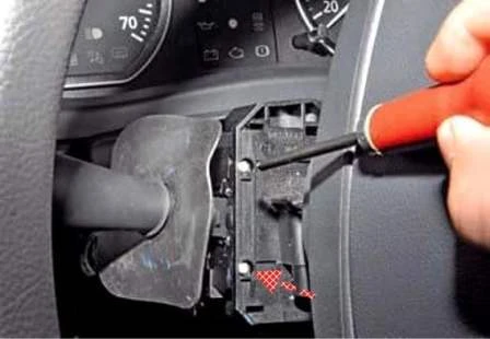
We turn the steering wheel to the left and with a cross-head screwdriver unscrew two screws securing the left steering column switch.
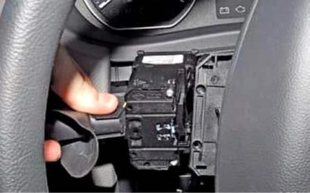
We take the left switch out of the connection.
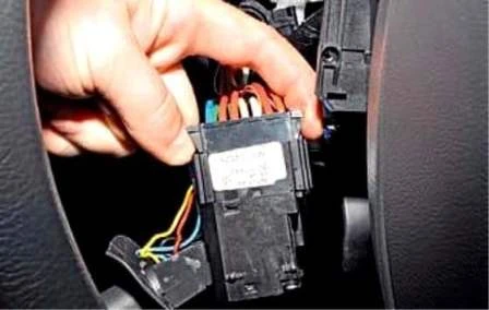
We squeeze two retainers of the wire connector.
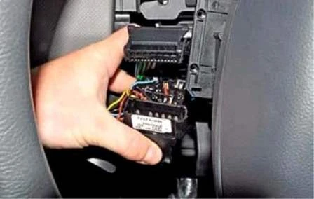
We disconnect the wire connector from the switch and remove the left steering column switch.
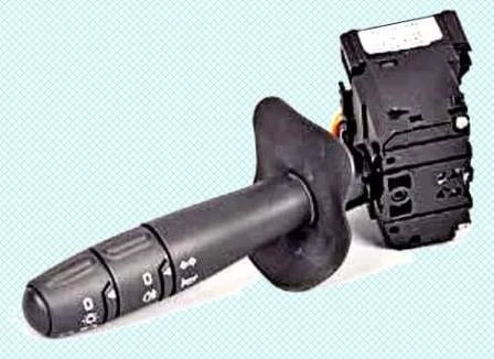
To remove the right steering column switch we remove the immobiliser coil.
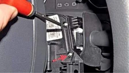
We turn the steering wheel to the right and with a cross-head screwdriver unscrew two screws securing the right steering column switch (the audio system remote control is removed for clarity).
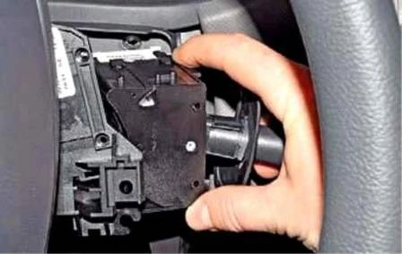
We take the switch out of the connector.
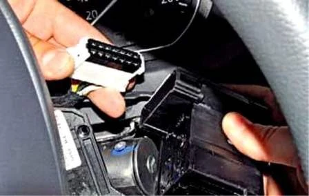
Having squeezed two retainers of the wire connector, we disconnect the connector from the switch.
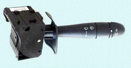
We remove the right steering column switch.
Installation
We install the steering column switches in the reverse order.
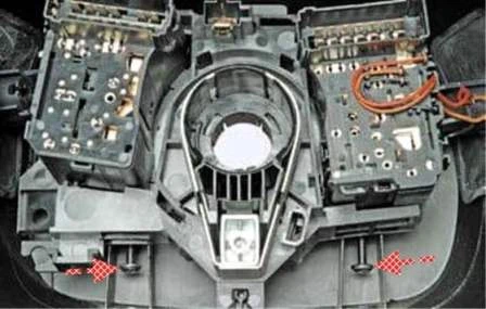
When installing the steering column shrouds, we pass the shroud securing screws through the openings in the bosses of the connector body of the steering column switches (shown for clarity on the removed shrouds and connector of the steering column switches).
To remove the connector of the switches with the drum device, we set the front wheels to the position corresponding to straight-line motion of the car.
We remove the steering wheel (article — Removing and installing the steering wheel of the car).
Before removing the connector of the steering column switches with the drum device of the spiral cable (for convenience of subsequent assembly), it is better to lock the drum of the device against turning.
To do this, if necessary, we turn the drum by a small angle, aligning the hollow between the two protrusions of the drum with the slot of the body.
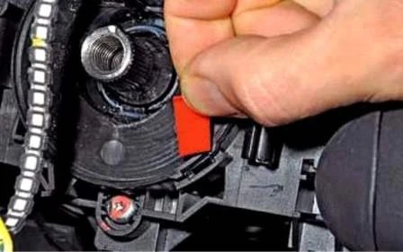
And we insert a plastic plate. A wooden wedge can also be inserted.
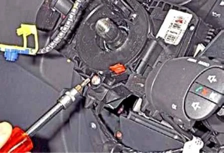
With a Torx T-20 key we unscrew the screw securing the connector.
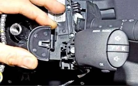
We remove the cover of the audio system remote control.
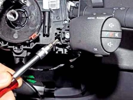
With a Torx T-20 key we unscrew the screw securing the remote control.
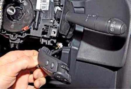
We remove the remote control from the connector of the switches and leave it hanging on the wires.
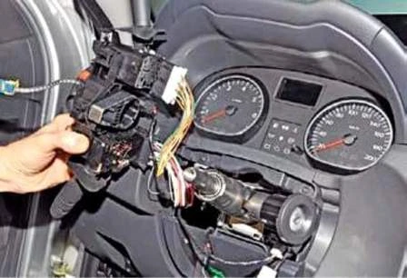
We move the connector of the switches off the steering column.
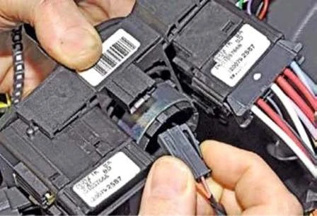
Having pressed the wire connector retainer, we disconnect the connector from the connector socket.
Having disconnected the connectors of the wires and the steering column switches, we remove the connector with the switches assembled.
We install the connector with the drum device and switches in the reverse order.
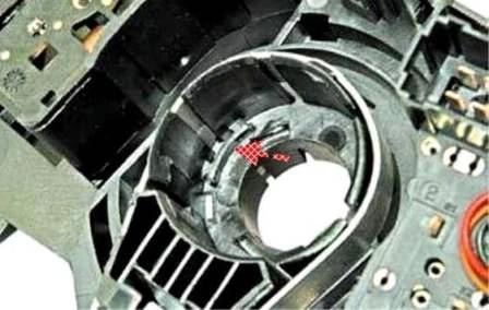
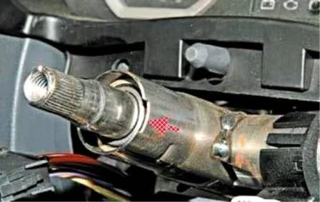
When installing the connector, we align the protrusion in the body seat of the connector with the slot on the end of the steering column tube.


