


In most cases, repairing the cylinder head consists of grinding in or replacing the valves and their guides, replacing or grinding the valve seats.
Moreover, to carry out work related to the repair of valve guides and seats, special tools and equipment are required.
In the event of faults such as loss of tightness of the cooling jacket channels and warping of the mating surface to the cylinder block, the cylinder head is replaced.
For the task the following tools are required: 10, 12, 17 spanners, spark plug spanner, magnetised flat-blade screwdriver (or tweezers) for removing valve spring keepers, valve spring compressor.
Prepare the vehicle for the work.
Remove the exhaust manifold (article – Removing the exhaust system components Renault Duster).
Remove the intake pipe and the fuel rail (article – Removal and installation of the engine receiver Renault Duster).
Check the operation of the hydraulic tappets; if necessary, wash them or replace them with new ones (article – Removal of the camshafts and valve hydraulic tappets Renault Duster).
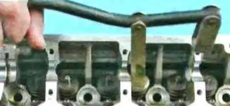
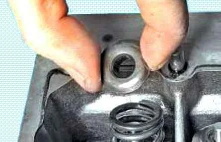
Fit the valve spring compressor, compress the springs, remove the keepers from the spring retainer.
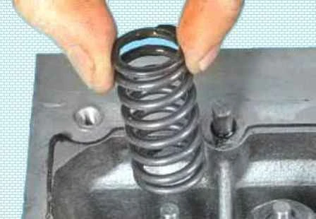
Springs (see «Replacing the valve stem seals Renault Duster»).
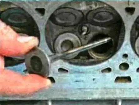
Withdraw the valves from their guides.
After prolonged operation, a mushroom-shaped burr may form on the upper end of the valve.
Before withdrawing the valve from the guide, remove this burr with a file.
It is prohibited to knock the valve out of the guide with a hammer through a drift without removing the burr, as this will inevitably damage the inner surface of the guide.
Remove resinous deposits from the upper surface of the head and from the intake ports.
These deposits can be softened and washed off with kerosene or diesel fuel.
Clean the combustion chambers and exhaust ports of carbon deposits.
Remove carbon deposits with a round metal brush fitted in the chuck of an electric drill.
Soak the carbon deposits in kerosene beforehand.
Clean the inner surfaces of the valve guides with a thin cylindrical brush made of copper wire clamped in the chuck of an electric drill.
Remove the burnt remains of the gasket from the mating surface of the head to the cylinder block.
It is prohibited to clean the mating surface of the head with metal brushes or sandpaper.
Use a scraper made of hard wood or plastic, after softening the gasket remains with solvent.
After cleaning, inspect the cylinder head to avoid operating it with damaged threaded holes, cracks (especially between the valve seats and in the exhaust ports), corrosion, inclusions of foreign materials, blowholes and pinholes.
Using a feeler gauge and a metal ruler placed on edge, check the flatness of the mating surface of the head to the block in the longitudinal and transverse directions, as well as along the diagonals.
If the gap between the edge of the ruler and the surface of the head exceeds 0.05 mm, replace the head.
Clean the flange surfaces of the head for fitting the intake pipe and exhaust manifold of gasket remains and carbon deposits.
Check for deformation of the mounting flanges of the intake pipe and exhaust manifold; replace a deformed head.
Repair damaged threaded holes by re-cutting the thread with taps or by fitting a repair insert (thread insert).
Determine the wear of the valve guides by measuring the inner diameter of the guide bore and the diameter of the valve stem, and determining the clearance from the difference of these dimensions.
The maximum permissible wear clearance is 0.10 mm for intake valves and 0.15 mm for exhaust valves.
If the clearance remains greater than the maximum permissible value even with new valves fitted, replace the guides.
Replace the guides in a specialised workshop that has the appropriate tools and equipment.
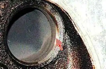
Check the condition of the valve seats.
There must be no traces of wear, blowholes, corrosion or other defects on the working chamfers of the seats.
The valve seats can be replaced in a specialised workshop.
Minor damage (small scores, scratches, etc.) can be removed by grinding in the valves.
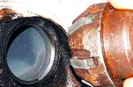
More significant defects of the valve seats are removed by grinding.
The seats must be ground in a specialised workshop, as this requires special tools and equipment.
If significant defects of the seats cannot be removed by grinding, replace the seats.
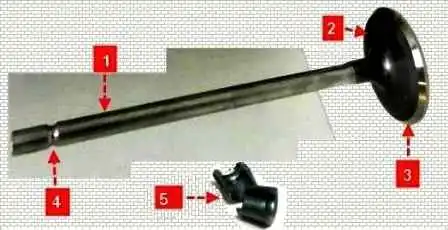
Remove carbon deposits from the valves and inspect them.
Deformation of the valve stem 1 and cracks in its head 2 are not permitted.
If there is damage, replace the valve.
Check whether the working chamfer 3 is too worn or damaged.
Grinding of the working chamfer of the valves is permitted (in repair workshops with the appropriate equipment).
After grinding, the thickness of the cylindrical part of the head must be at least 0.5 mm for intake valves and at least 1.0 mm for exhaust valves.
Minor scores and scratches on the chamfer can be removed by grinding the valve into its seat.
Check the concentricity of the valve head and the seat: apply a thin layer of paint (e.g. Prussian blue) to the chamfer of the valve head, insert it into the guide and, pressing it lightly against the seat, turn it.
The traces of paint on the chamfer of the seat indicate the concentricity of the valve and the seat.
Check the condition of the grooves on the valve stem for the keepers.
If traces of spalling of the edges of the grooves and wear of the cylindrical part are found, replace the valve.
Replace the valve stem seals regardless of their condition.
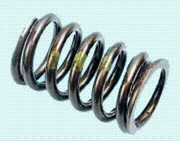
Inspect the valve springs.
Cracks and reduced spring elasticity are not permitted.
Springs of one of two types may be fitted.
The nominal free length of the first type spring is (46.52) mm, of the second type – (46.642) mm.
The length with fully compressed coils is respectively 26.0 and 23.63 mm.
Replace springs whose free length is less than the maximum permissible value, as well as bent springs (deviation of the spring axis from the vertical in the free state by more than 4°) and springs with cracks.
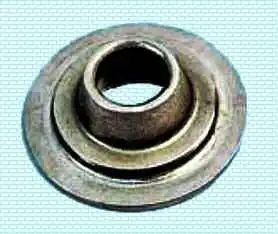
Check the condition of the spring retainers. Replace retainers with significant wear of the supporting grooves for the springs.
Refit all the removed parts and assemblies of the cylinder head in the reverse order of removal.
Always replace the cylinder head, intake pipe and exhaust manifold gaskets with new ones, as gaskets removed from the engine, even externally undamaged, may be heavily compressed and will not ensure a tight seal.
Grinding in the valves of the cylinder head
Grinding in the valves is carried out on the removed cylinder head. To withdraw the valves from the guides of the cylinder head, the valve springs must be removed by compressing them with a special tool and removing the keepers from the spring retainers (see «Replacing the valve stem seals Renault Duster»).
For grinding in the valves it is most convenient to use a special mechanical tool (reversible drill).
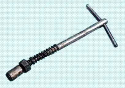
In addition, ready-made manual valve holders are available on the market.
If ready-made tools are not available, a tool made to a drawing can be used.

Instead of the rubber hose and clamps, an end piece can be welded to the rod of the tool, in the side wall of which a through threaded hole is made, into which a bolt is screwed to secure the valve stem.
In addition, you will need: grinding paste, kerosene, a weak spring that passes by its outer diameter into the hole of the valve seat.
Clean the valve of carbon deposits.
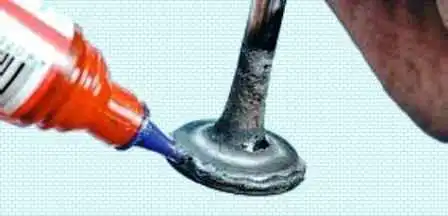
Apply a thin, continuous layer of grinding paste to the chamfer of the valve.
Fit the previously selected spring onto the valve stem and insert the valve into the guide from the combustion chamber side, after coating the valve stem with a layer of graphite grease.
The graphite grease protects the guide from abrasive from the grinding paste entering its holes and facilitates rotation of the valve during grinding.
Fit the valve grinding tool onto the valve stem (or, with some tension, a rubber tube to connect the valve to the reversible drill).
Switching the drill to the minimum rotational speed (in reversible mode) or turning the tool (in the case of manual grinding) alternately in both directions by half a turn, grind in the valve, periodically pressing it against the seat and then easing the pressing force.
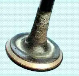
Grind in the valve until a continuous, uniformly matt-grey band at least 1.5 mm wide appears on its chamfer.
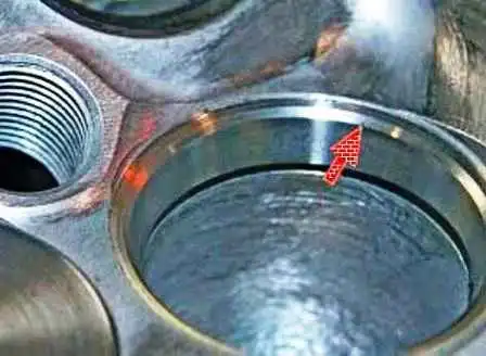
At the same time, a shiny band at least 1.5 mm wide must also appear on the valve seat after grinding.
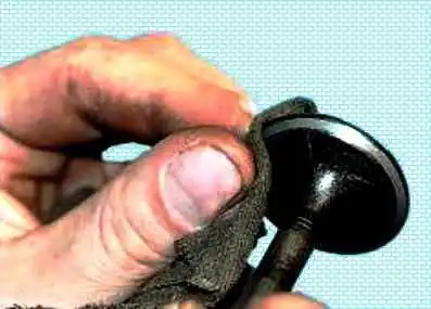
After grinding, wipe the valve and seat thoroughly with a clean cloth and wash to remove residues of the grinding paste.
Check the tightness of the valve by fitting it into the head with the springs and keepers.
Then place the head on its side and pour kerosene into the port closed by the valve.
If within 3 minutes the kerosene does not seep into the combustion chamber, the valve is tight.


