
The 2.0- and 2.4-liter gasoline engines are inline-four-cylinder units with dual overhead camshafts (DOHC). The cylinder head is equipped with a continuously variable valve timing (CVVT) system on the intake manifold.
Firing order: 1–3–4–2.
Main components:
Cylinder block: made of cast iron.
Cylinder head and water pump housing: made of aluminum alloy.
Crankshaft: forged steel, has five support (main) bearings.
Piston group: pistons are cast from a special aluminum alloy and connected to the connecting rods via a floating pin. The piston rings are cast iron.
- The upper (first) compression ring has a barrel-shaped running surface.
- The second compression ring is conical with a bevel.
- The oil scraper ring is composite, scraper-type, with a spring expander.
The combustion chambers in the cylinder head are of the tent-type.
Valves: Intake and exhaust are made of heat-resistant steel. The valves are actuated by tappets. The clearance is adjusted using special adjusting washers with a wear-resistant coating where they contact the camshaft lobe.
Timing Drive: Each cast camshaft rotates in five bearings and is driven by a chain from the crankshaft.
Engine Specifications:

Changeable Valve Timing System (CVVT) (for models before 2009)
CVVT System (*Continuously Variable Valve Timing*) provides smooth change of valve timing in accordance with the engine operating mode. This is achieved by rotating the intake camshaft relative to the exhaust camshaft by up to 50° (crankshaft rotation angle).
Operating diagram of the CVVT actuator:

As a result, the moment the intake valves begin to open and the duration of the **"overlap"** period of the valves (the time when the exhaust valve is not yet closed and the intake valve is already open) changes.
Application CVVT improves cylinder filling efficiency and reduces nitrogen oxide (NOx) emissions through internal exhaust gas recirculation (EGR) in all engine operating modes.
Since 2009, the CVVT system has also been installed on the exhaust camshaft.
CVVT Design and Operation
The CVVT actuator is mounted on the camshaft. Its housing is connected to the drive sprocket, and the rotor is directly connected to the shaft.
To rotate the shaft, pressurized engine oil is supplied to one side of the rotor blades through an oil control valve (OCV). At the same time, the opposite side of the rotor is connected to a drain. Once the desired position is reached, both channels close, locking the shaft.


Valve timing diagram: EX — exhaust valve, IN1 — intake valve with late opening, IN2 — intake valve with early opening.
When the engine is stopped, the maximum retard angle (latest valve opening) is set. To prevent the mechanism from shaking during startup (when oil pressure is still low), the rotor is secured in the housing with a locking pin, which is subsequently forced out by oil pressure.

Operation in Various Modes:

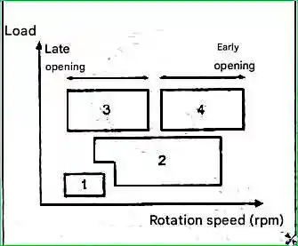
- 1. Idle and Low Load: Minimal valve overlap is established to prevent exhaust gases from entering the intake tract and causing fuel loss.
- 2. Medium Load: Early closing of the intake valves is ensured to improve cylinder filling and increase torque.
- 3. High Load, Low/Medium RPM: Sets minimum overlap for optimal performance.
- 4. High Load, High RPM: Provides late intake valve closing for improved filling at high RPM and increased power.
Results of using the CVVT system:
- - Increases torque at low and mid-range RPM.
- - Increases maximum power.
- - Stabilizes idle speed, improving fuel economy.
- - Improves engine starting.
Limp Home Mode: In the event of a system malfunction, control is disengaged and the camshaft is fixed at the maximum retard angle.

")
")
")
")
")
")
")
")