


In this article we consider the operations of dismantling and repairing the engine cylinder head.
Dismantling the cylinder head
We wash the cylinder head and place it on the workbench or in the dismantling fixture.
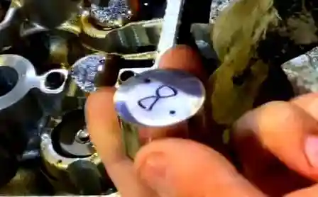
We remove the valve tappets from the cylinder head and mark their position relative to the cylinder head.
Using the fixture, we compress the valve springs and remove the split collets with tweezers.
We press out the valve stem seals using special pliers or an inertia puller.
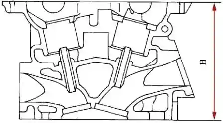
We check the cylinder head height.
The height H (figure) of the cylinder head must be 125 mm.
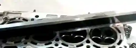
Using a straight edge and a set of feeler gauges, we check the flatness of the cylinder head surface that mates with the cylinder block.
The maximum permissible non-flatness of the cylinder head mating surface is 0.1 mm.
We check the diameter of the camshaft supports; to do this:
- we install on the cylinder head the centring sleeves and the camshaft bearing caps;
- we tighten the cap fastening bolts to a torque of 9.0–11.0 N·m (0.9–1.1 kgf·m).
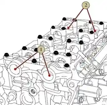
Using the НИ 18-50-1 bore gauge, we measure the bores for each cap.
The bore diameter for the first cap 1 (figure) must be 28.000–28.021 mm; for the bores 2 of the remaining caps — 25.000–25.021 mm.
After this we unscrew the fastening bolts and remove the camshaft bearing caps and the centring sleeves.
We check the bore diameter of the valve guides.
The maximum permissible diameter must not be greater than 5.03 mm.
We check the diameter of the tappet seats in the cylinder head.
The seat diameter must be 30.000–30.021 mm.
We check the outer diameter of the valve tappets.
The tappet diameter must be within 29.977–29.987 mm.
On the tappet surface there must be no wear marks or coating cracks.
Checking the valves
One-sided wear of the valve stem on the working surface is not permitted.
We visually determine the wear and condition of the valve heads. Chipping, cracks and one-sided wear are not permitted.
We determine the wear of the valve stem end; if necessary, the end can be ground.
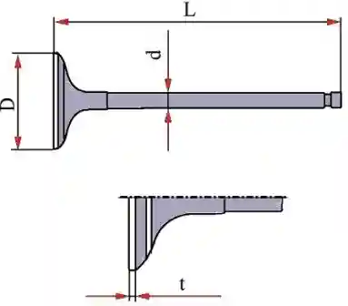
The permissible valve dimensions are given in the figure and in the table.
Permissible valve dimensions
| Parameter | Inlet valve | Exhaust valve |
|---|---|---|
| Valve head diameter D, mm | 31.6±0.15 | 25.3±0.15 |
| Valve stem diameter d, mm | 4.965–4.980 | 4.955–4.970 |
| Valve length L, mm | 101.48 | 102.24 |
| Height of the cylindrical part of the valve head t, mm | 1.00 | 1.00 |
Checking the valve springs
Free length of the spring — 42.26 mm.
Length of the spring under a load of 145±9 N (14.5±0.9 kgf) — 34.4 mm.
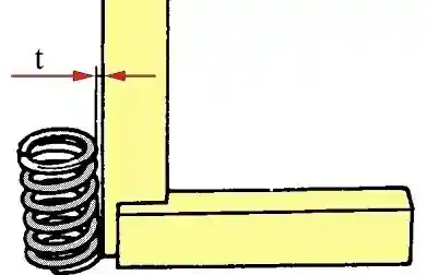
The deviation “t” (figure) of the spring from perpendicularity must not exceed 1.6 mm.
We check the valve seats and lap the valves in.
After this we wash and blow out all the bores and parts of the cylinder head.
Assembling the cylinder head
We install the inlet and exhaust valves in the cylinder head.
To do this, we install the cylinder head on the fixture 67.7823-9567 for removing and installing the valve split collets.
We lubricate the valve stems with engine oil.
Using the drift 67.7853-9732, we press in the valve stem seals until they stop against the supporting surface of the cylinder head.
We install the spring support washers in the cylinder head.
We install the valve springs and the spring retainers.
We lubricate the outer surfaces of the tappets with engine oil and install the tappets in the cylinder head in accordance with the marking.
Using a stud driver, we screw into the cylinder head the new exhaust manifold fastening studs, with the short part into the head body.
We remove the cylinder head from the fixture.
Installing the cylinder head
We press two cylinder head centring sleeves into the cylinder block (if they are not installed).
The protrusion of the sleeve above the mating surface of the cylinder block is 6–8 mm.
We apply two dots of sealant to the surface of the cylinder block on the timing drive side, as shown in the figure.
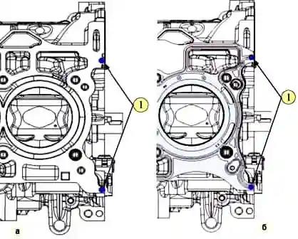
We install a new cylinder head gasket on the cylinder block and apply two dots of sealant to the gasket on the timing drive side, as shown in the figure.
We use silicone sealant TB1217L, consumption — 1 gram.
We screw the crankshaft pulley fastening bolt into the crankshaft and set the pistons at mid-stroke.
We install on the cylinder block the cylinder head, the cylinder head fastening bolt washers, and the new fastening bolts.
We screw in and tighten the cylinder head fastening bolts.
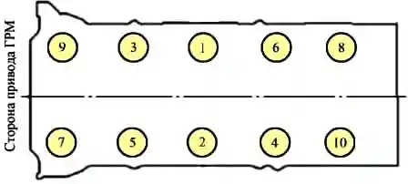
Carry out the tightening of the cylinder head fastening bolts in the order shown in the figure, in the following sequence (11 socket, handle, extension, torque wrench, angle gauge):
- tighten the bolts to a torque of 35.0–44.0 N·m (3.5–4.4 kgf·m);
- turn the bolts a further 60°–65°;
- loosen all the bolts;
- tighten the bolts to a torque of 35.0–44.0 N·m (3.5–4.4 kgf·m);
- turn the bolts a further 75°–80°.


