


If there is play in the ball joints or if the protective rubber boots are damaged, the ball joints must be removed and replaced.
Replacing the upper ball joint
We prepare the vehicle for the task.
Place wheel chocks under the rear wheels.
Raise the front of the vehicle with a jack, support it on robust stands, and remove the corresponding wheel.
Place a jack under the lower control arm of the front suspension and raise it by a few centimetres to simulate the working load.

Unscrew the nut of the upper ball joint pin.
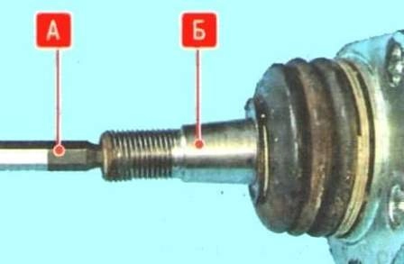
If the ball joint pin «Б» turns in the conical hole of the steering knuckle, hold it with an Allen key «А» inserted into the axial hole at its end (shown on a removed joint for clarity).

Using a separator, extract the joint pin from the conical hole of the steering knuckle.
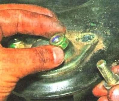
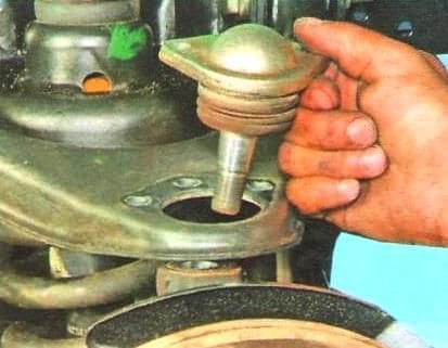
Install the new ball joint in the reverse order.
Replacing the lower ball joint
Required tools: 17 mm and 30 mm spanners, hammer, pliers, ball joint pin separator.
Prepare the vehicle: place wheel chocks under the rear wheels, raise the front with a jack, support it on robust stands, and remove the wheel.
Place a jack under the lower arm and raise it by a few centimetres.
Important: The lower ball joint can only be removed and installed when the steering knuckle is dismantled.
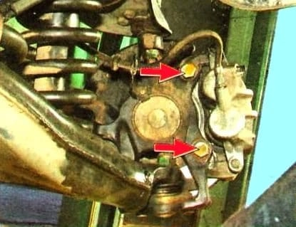
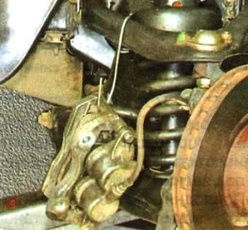
Unscrew the two caliper mounting bolts. Remove the caliper and securely tie it to the suspension components with wire, absolutely avoiding letting it hang by the brake hose.
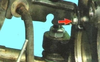
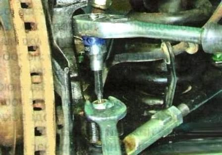
Unscrew the nut securing the tie rod joint pin to the steering knuckle arm, holding the pin to prevent it from turning.
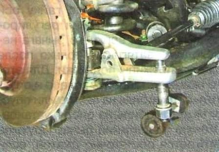
Install the ball joint separator and extract the pin from the boss of the steering knuckle arm.
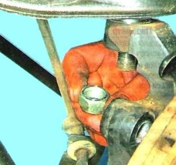
Unscrew the nut of the upper ball joint pin. If the ball joint pin turns, hold it with an Allen key inserted into the axial hole at its end.


Unscrew the two bolts securing the lower ball joint to the steering knuckle and remove the steering knuckle with the hub assembly.
Unscrew the nut securing the ball joint pin.


Important: Before screwing the joint mounting bolts into the steering knuckle, be sure to clean the threads and holes of any old sealant and degrease them.
Apply anaerobic thread locker to the threaded part of the bolts.
Tighten the bolts securing the lower ball joint to the steering knuckle to a torque of 80–100 N·m.