During operation, the ignition switch is subjected to high mechanical and electrical loads, which is why the contact or mechanical part of the lock fails.
To replace the ignition switch, you will need a 10 mm socket head, screwdrivers, a thin, sharp chisel, a hammer, and new bracket mounting bolts.
Disconnect the negative terminal of the battery.
Remove the steering wheel
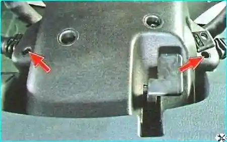
Unscrew the two screws in the recesses of the lower part of the casing
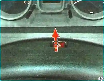
Pull up and remove the upper part of the casing
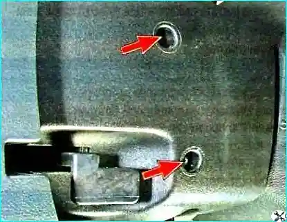
Unscrew the two screws securing the lower part of the casing to the steering column
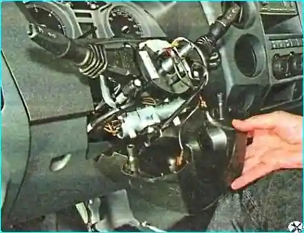
Remove the lower part of the casing
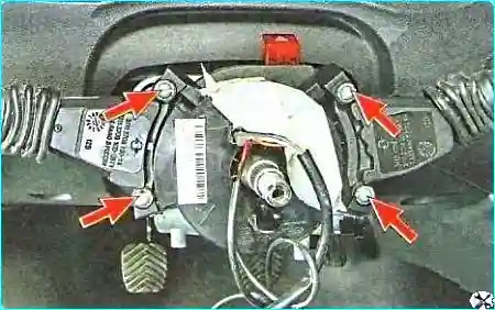
Unscrew the four screws securing the steering column switches
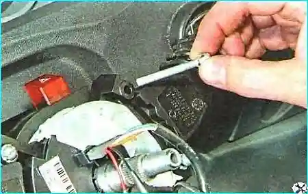
Remove the screws from the holes
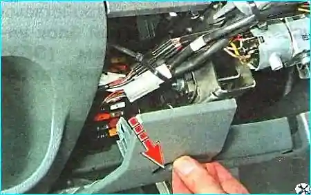
Removing the lower decorative trim of the instrument panel
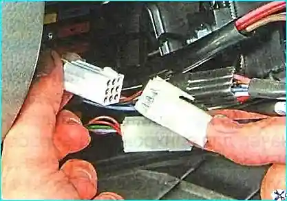
Disconnecting the white block of wires of the left steering column switch
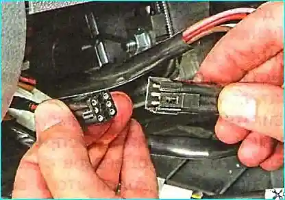
Also disconnect the black block of wires of the right steering column switch
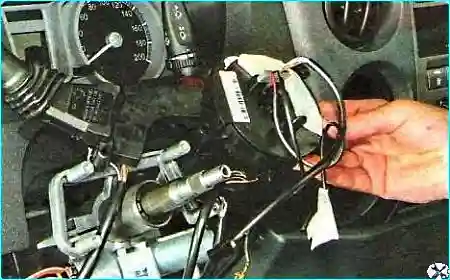
Removing the switch block
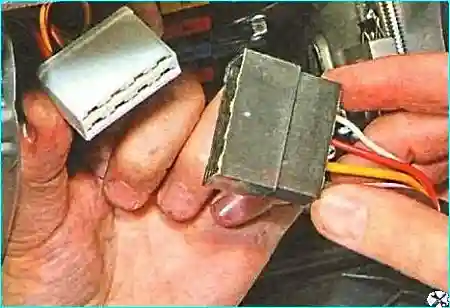
Disconnect the instrument switch wiring block
The elements described above must be removed to gain access to the ignition switch mounting bolts.
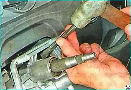
Use a chisel to unscrew the two bolts with shear heads
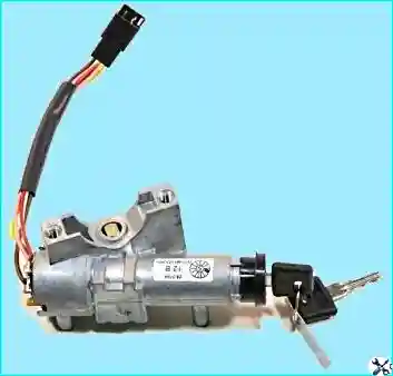
Removing ignition switch
Install the ignition switch in the reverse order, using new bolts.
To replace the switch contact group:
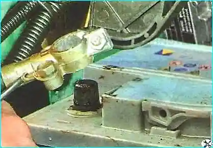
- - disconnect the negative terminal from the battery
When removing the retaining ring, the terminals of the contact group may be accidentally short-circuited with a tool or ring.
In this case (if the battery is connected), an unauthorized engine start may occur! And if at this moment the gear is also engaged, the car may start moving spontaneously.
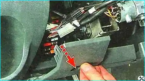
Removing the lower decorative panel

Disconnect the switch wiring harness connector ibor
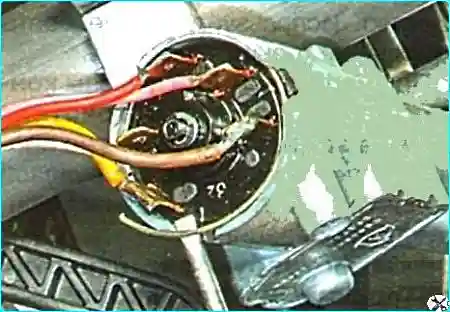
Use a thin screwdriver to pry off the retaining ring
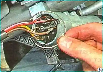
Remove the retaining ring
Remove the contact group
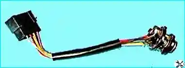
After removing the contact group from the switch housing, the starter lock pawl spring may fall out when the engine is running. Do not lose it. Without a spring, the lock will not work.
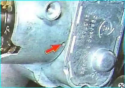
Before installing the contact group in the switch housing, press the starter lock pawl with the engine running.
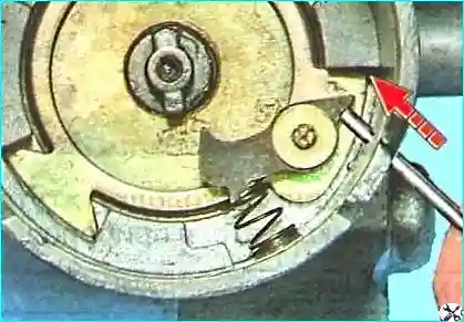
To do this, press a thin pin through the technological hole in the housing onto the stop pawls
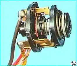
Keeping the pawl pressed down, install the contact group in the reverse order of removal.
The retaining ring should fit securely into the groove of the switch bracket.
If the new contact group does not have a wiring harness, unsolder the wires from the terminals of the contact group being replaced and solder them to the terminals of the new contact group in the following order:
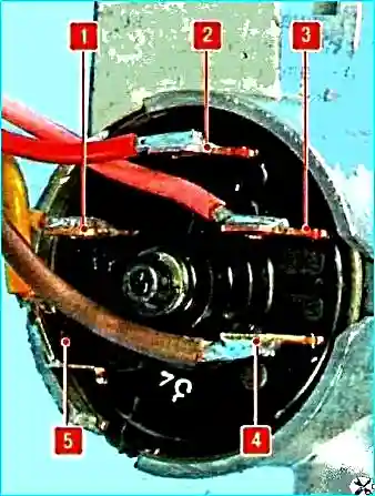
- 1 — white wire to terminal 50;
- 2 — red wire to terminal 15-1;
- 3 — pink wire to terminal 30-1;
- 4 — brown wire to terminal 15-2;
- 5 — yellow wire to terminal 30.


