The belt replacement period, regardless of its condition, is 60 thousand kilometers or four calendar years, whichever comes first
A broken belt can cause significant engine damage.
Engine pistons and valves can be severely damaged.
The valves are either broken or bent, and the pistons are destroyed. The connecting rods also get damaged.
When inspecting the belt, you need to pay attention so that there are no cracks, cuts, delaminations.
The surface of the belt must be free of oil.
On K4M engines, the pulleys do not have alignment marks, so you need to have special tools for setting the camshafts to the TDC position of the first cylinder and a special pin to fix the crankshaft at the TDC of the first cylinder.
Devices, of course, can be made by yourself according to the drawings given in this article.
Preparing the car for the task. We install it on a lift or a viewing ditch.
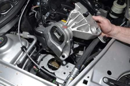
Remove the right support of the power unit for this:
We substitute a jack under the oil pan through a wooden or rubber block.
We remove the fuel pipes from the holders located on the support bracket
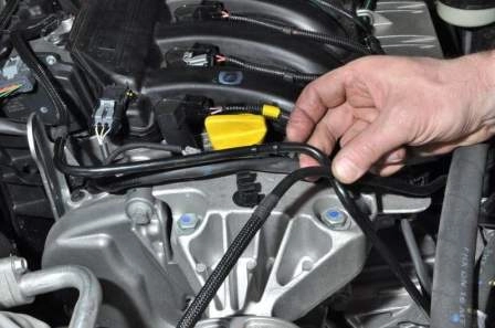
Remove the wire harness holder from the support bracket hole
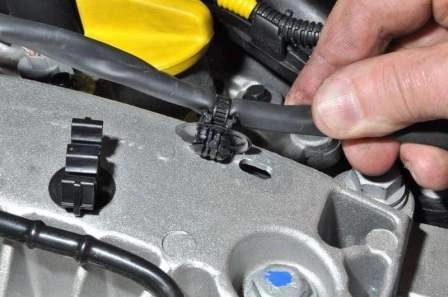
With a 16 head, unscrew the three bolts securing the support bracket to the top cover of the timing drive
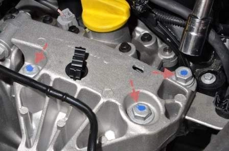
We unscrew the three bolts securing the support to the body
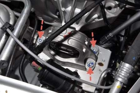
Removing the right support
Removing the right mudguard (article - Removing the protection of the Nissan Almera power unit)
Checking and replacing the belt on the K4M 1.6L engine
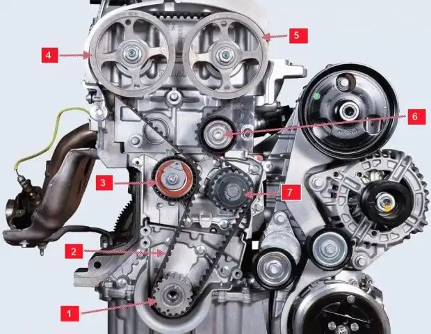
The location and installation of the belt is shown in Figure 6.
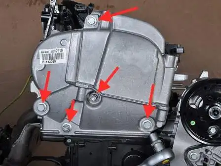
With a 13 head, unscrew the three bolts and two nuts securing the upper timing cover
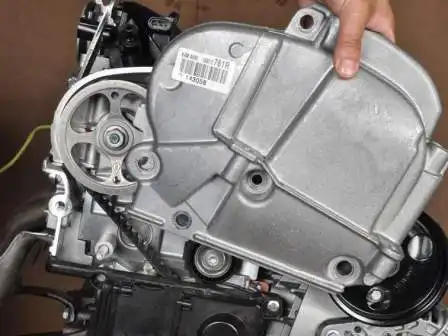
Remove the top cover
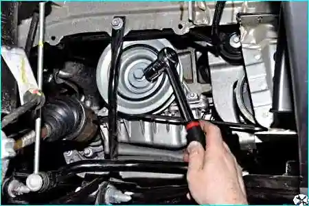
With a head of 18, turn the crankshaft clockwise and inspect the timing belt
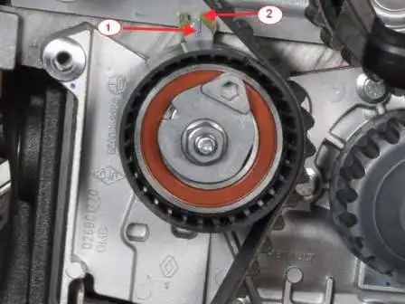
At normal belt tension, pointer 1 should align with the notch of pointer 2 of the tensioner
If the movable pointer is offset from the fixed pointer, then tighten the belt.
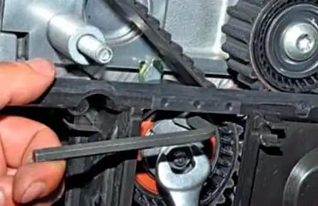
We loosen the tightening of the tension roller fastening nut with a 13 wrench and turn the roller clockwise with a hexagon by 6, pulling the belt until the pointers align.
While holding in this position, tighten the roller nut.
To replace the belt, remove the accessory belt (Replacing the accessory belt Nissan Almera)
Remove the top timing cover
We turn on the fifth gear and the assistant presses the brake pedal
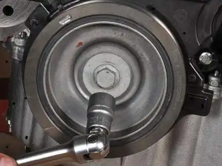
With a head of 18, we unscrew the bolt securing the accessory drive pulley
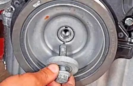
Removing the bolt with washer
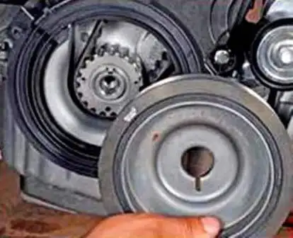
Remove the accessory drive pulley
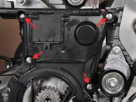
With a head of 8, unscrew the four bolts securing the lower timing cover
Remove the cover
Set the crankshaft and camshafts to the top dead center of the first cylinder.
To do this, unscrew all the candles.
We screw the bolt of the accessory drive pulley into place by installing a set of suitable washers.
To determine the position of the camshafts, it is necessary to remove the plugs from the holes in the left end of the cylinder head.
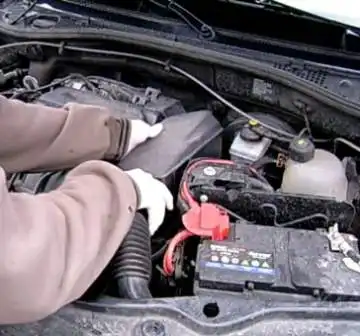
Remove the air intake with a resonator
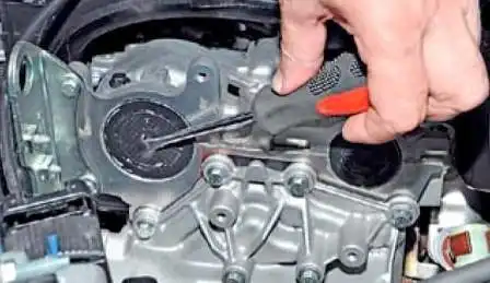
In the center of the plug, pierce a hole with a screwdriver
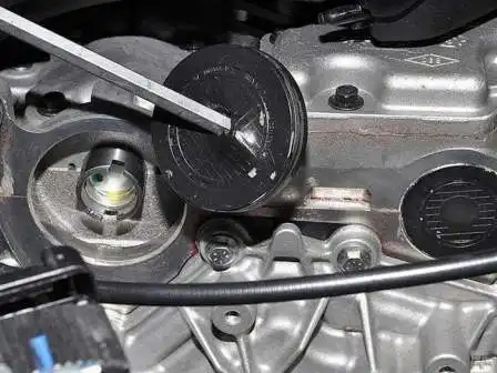
Remove the plug from the hole in the cylinder block.
Also extract another stub
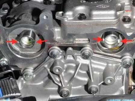
Turn the crankshaft clockwise, the grooves on the ends of the camshafts should take a horizontal position, and shifted down relative to the axes of the camshafts
To fix the camshafts in this position, a device can be made from a metal plate five millimeters thick.
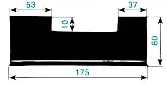
The dimensions of the fixture are shown in the figure
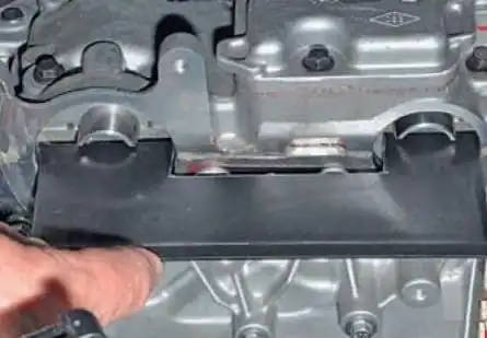
Install the device in the grooves of the shafts
We check that the crankshaft is in the TDC position of the pistons of the 1st and 4th cylinders. For this:
Unscrew the plug with the E14 head
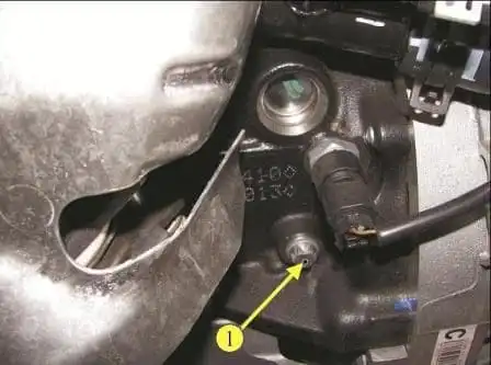
Insert the installation pin into the hole (shown with the pallet removed)
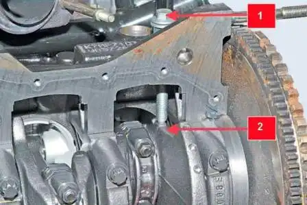
When the crankshaft is in the TDC position of the pistons of the 1st and 4th cylinders, the mounting pin 1 must be screwed into the hole to the end of the thread and abut against the milled area 2 on the crankshaft web.
After that, the crankshaft will be impossible to turn.
If, when screwing in the adjusting pin, it rests, and the end of the adjusting nut on the pin does not come into contact with the end face of the boss of the hole in the cylinder block (there will be a gap between the nut and the boss), then you need to turn a little (by removing the device from the grooves of the camshafts) crankshaft shaft counterclockwise.
Then you need to screw the mounting pin into the hole of the cylinder block to the end (until the ends of the pin nut and the boss of the hole in the block touch) and turn the crankshaft clockwise until the platform of the shaft cheek stops against the pin.
Install the camshaft locking tool, if it was removed.
An M10 bolt can be used as a mounting pin
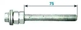
We screw two adjusting nuts onto the bolt and lock them so that the length of the threaded part of the bolt is 75 mm.
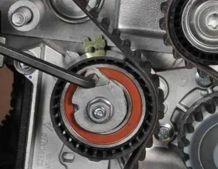
Turn the roller counterclockwise, reducing the tension of the timing drive
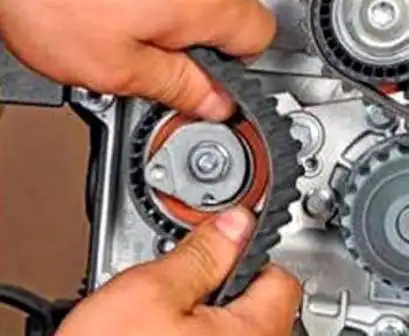
Remove the belt from the tensioner
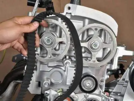
Remove the belt from the coolant pump pulleys, crankshaft and camshafts

Belt marking (number of teeth 131, width 25.4 mm)
When replacing the belt, it is advisable to replace the tension and support roller, for this we unscrew the tension roller fastening nut
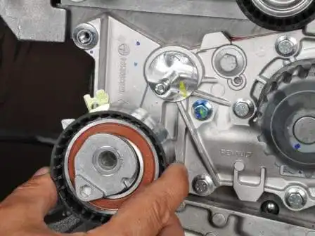
Remove the tension roller from the coolant pump housing stud
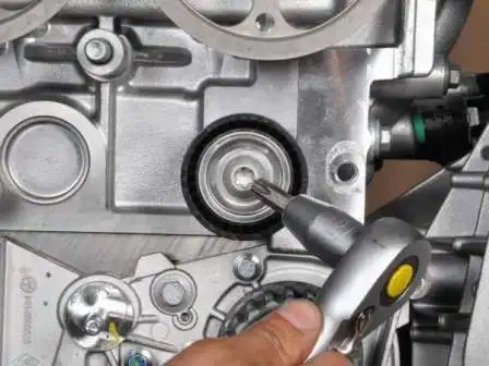
Use the TORX T50 key to unscrew the screw securing the support roller
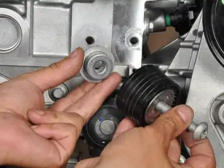
Remove the support roller and its bushing.
Installing the timing belt
We orient the belt so that the arrows on the belt coincide with the direction of movement of the belt clockwise.
We install the belt on the gear pulleys of the crankshaft, coolant pump, camshaft pulleys.
Then, at the same time, we put the belt on the tension roller and install the roller on the stud of the coolant pump housing.
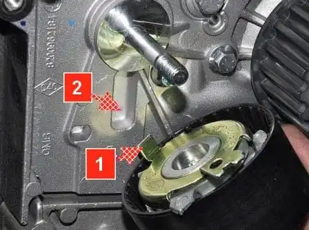
When installing the tension roller, insert the bent end 1 of the roller bracket into recess 2 of the coolant pump housing.
Adjust the belt tension as described above.
Unscrew the locking pin from the hole in the cylinder block and remove the ficamshaft alignment.
Rotate the crankshaft two turns clockwise until the grooves on the camshafts take the position corresponding to the top dead center of the 1st piston.
We twist the plug into the hole in the cylinder block.
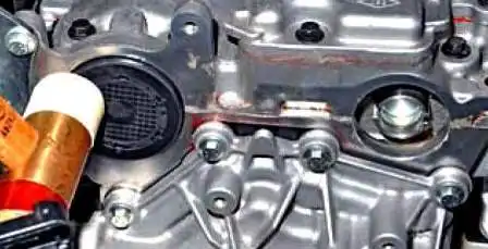
With light blows of a hammer with a plastic striker, we press new plugs into the holes of the cylinder head.
Assemble the parts in reverse order. We replace the auxiliary drive pulley bolt with a new one and tighten it with a torque of 40 Nm, then tighten it by 110˚.
- We tighten the bolt for fastening the bracket for the tension roller of the auxiliary drive belt with a torque of 21 Nm.
- We tighten the bolt for fastening the timing belt support roller with a torque of 50 Nm.
- Tighten the timing belt tensioner pulley nut with a torque of 28 Nm.
- We tighten the M8 bolt for fastening the upper timing cover with a torque of 22 Nm.
- We tighten the M10 bolt for fastening the upper timing cover with a torque of 44 Nm.
- We tighten the bolt for fastening the lower timing cover with a torque of 8 Nm.


