


The phaser is designed to alter the valve timing.
To improve cylinder filling under all operating conditions, K4M and F4R engines are equipped with an intake camshaft phaser (Fig. 1).
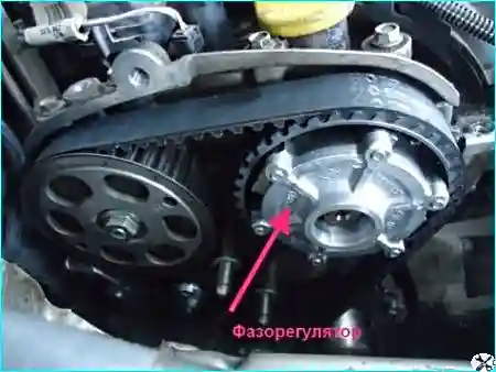
Fig. 1. Intake camshaft phaser
Shifting the intake valve closing point optimises cylinder filling as a function of crankshaft speed.
This increases torque under medium loads and power at high engine speeds.
Under these conditions, later closing of the intake valves allows an additional charge of mixture to enter, due to its high flow velocity.
Conversely, at low engine speeds, charge inertia is low.
Earlier closing of the exhaust valves prevents poor cylinder filling and loss of torque due to part of the fresh mixture charge being pushed out.
The higher the crankshaft speed, the later the intake valves should close.
Phaser operating modes (K4M engine)
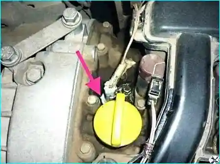
Fig. 2. Phaser solenoid valve
Oil is supplied to the phaser via a solenoid valve mounted on the cylinder head (Fig. 2).
The valve is supplied with a variable duty cycle signal (12 V, 250 Hz), which allows oil to be directed to the mechanism and thus change the phase angle.
The ECU drives the solenoid valve with a variable duty cycle signal, the value of which is proportional to the required phase shift.
The phase angle varies continuously from 0 to 43° of crankshaft rotation.
The camshaft phaser solenoid valve is controlled when the following conditions are met:
- no fault from the crankshaft speed sensor;
- no faults from the camshaft position sensors;
- no faults in the injection system;
- after engine start;
- engine not running at idle with the accelerator pedal released;
- the threshold value of the injection profile (set according to load and engine speed) has been reached;
- coolant temperature between 10 and 120 °C;
- engine oil temperature is elevated.
Backup modes:
- phaser return to initial position;
- zero phase shift.
If the solenoid valve jams in the open position, the engine runs roughly at idle, the intake manifold pressure is high, and engine noise is increased.
Phaser operation and control (F4R engine)
The phaser is either inactive or controlled by the injection ECU via a solenoid valve mounted on the cylinder head cover (Fig. 3).
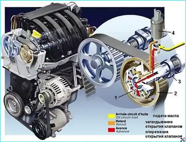
Fig. 3. Phaser operation: 1 - phaser rotor, 2 - phaser gear, 3 - intake camshaft, 4 - phaser solenoid valve
When the crankshaft speed is between 1500 and 4300 rpm, the ECU supplies voltage to the solenoid valve.
Above 4300 rpm, the voltage supply to the solenoid valve is cut off.
In this case, the position of the phaser mechanism promotes cylinder filling at high engine speeds.
In this position, the locking plunger locks the mechanism.
At speeds below 1500 rpm, no voltage is supplied to the solenoid valve.
The mechanism is locked by the plunger.
As soon as voltage is applied to the solenoid valve (speeds above 1500 rpm), oil pressure moves the locking plunger back, releasing the mechanism.
In the initial position, the solenoid valve is closed.
The valve opens the oil passage to control the phaser when the following conditions are met:
- no fault from the crankshaft speed sensor;
- no faults from the camshaft position sensors;
- no faults in the injection system;
- after engine start;
- engine is not idling;
- battery voltage above 11.4 V;
- coolant temperature above 30 °C;
- engine speed between 1500 and 4300 rpm;
- load greater than 87% (approx. 900 mbar).
If the solenoid valve jams in the open position, the engine runs roughly at idle and the intake manifold pressure is high.


